BOOK: SOFTWARE ENGINEERING FOR SELF-DIRECTED LEARNERS
- SECTION: INTRODUCTION
- SECTION: OOP (with UML)
- SECTION: REQUIREMENTS
- SECTION: DESIGN
- SECTION: IMPLEMENTATION
- SECTION: QUALITY ASSURANCE
- SECTION: PROJECT MANAGEMENT
- SECTION: TOOLS
- SECTION: SUPPLEMENTARY
SECTION: INTRODUCTION
Software Engineering
Software Engineering: Software Engineering is the application of a systematic, disciplined, quantifiable approach to the development, operation, and maintenance of software" -- IEEE Standard Glossary of Software Engineering Terminology
The following description of the Joys of the Programming Craft was taken from Chapter 1 of the famous book
Why is programming fun? What delights may its practitioner expect as his reward?
First is the sheer joy of making things. As the child delights in his mud pie, so the adult enjoys building things, especially things of his own design. I think this delight must be an image of God's delight in making things, a delight shown in the distinctness and newness of each leaf and each snowflake.
Second is the pleasure of making things that are useful to other people. Deep within, we want others to use our work and to find it helpful. In this respect the programming system is not essentially different from the child's first clay pencil holder "for Daddy's office."
Third is the fascination of fashioning complex puzzle-like objects of interlocking moving parts and watching them work in subtle cycles, playing out the consequences of principles built in from the beginning. The programmed computer has all the fascination of the pinball machine or the jukebox mechanism, carried to the ultimate.
Fourth is the joy of always learning, which springs from the nonrepeating nature of the task. In one way or another the problem is ever new, and its solver learns something: sometimes practical, sometimes theoretical, and sometimes both.
Finally, there is the delight of working in such a tractable medium. The programmer, like the poet, works only slightly removed from pure thought-stuff. He builds his castles in the air, from air, creating by the exertion of the imagination. Few media of creation are so flexible, so easy to polish and rework, so readily capable of realizing grand conceptual structures....
Yet the program construct, unlike the poet's words, is real in the sense that it moves and works, producing visible outputs separate from the construct itself. It prints results, draws pictures, produces sounds, moves arms. The magic of myth and legend has come true in our time. One types the correct incantation on a keyboard, and a display screen comes to life, showing things that never were nor could be.
Programming then is fun because it gratifies creative longings built deep within us and delights sensibilities we have in common with all men.
Not all is delight, however, and knowing the inherent woes makes it easier to bear them when they appear.
First, one must perform perfectly. The computer resembles the magic of legend in this respect, too. If one character, one pause, of the incantation is not strictly in proper form, the magic doesn't work. Human beings are not accustomed to being perfect, and few areas of human activity demand it. Adjusting to the requirement for perfection is, I think, the most difficult part of learning to program.
Next, other people set one's objectives, provide one's resources, and furnish one's information. One rarely controls the circumstances of his work, or even its goal. In management terms, one's authority is not sufficient for his responsibility. It seems that in all fields, however, the jobs where things get done never have formal authority commensurate with responsibility. In practice, actual (as opposed to formal) authority is acquired from the very momentum of accomplishment.
The dependence upon others has a particular case that is especially painful for the system programmer. He depends upon other people's programs. These are often maldesigned, poorly implemented, incompletely delivered (no source code or test cases), and poorly documented. So he must spend hours studying and fixing things that in an ideal world would be complete, available, and usable.
The next woe is that designing grand concepts is fun; finding nitty little bugs is just work. With any creative activity come dreary hours of tedious, painstaking labor, and programming is no exception.
Next, one finds that debugging has a linear convergence, or worse, where one somehow expects a quadratic sort of approach to the end. So testing drags on and on, the last difficult bugs taking more time to find than the first.
The last woe, and sometimes the last straw, is that the product over which one has labored so long appears to be obsolete upon (or before) completion. Already colleagues and competitors are in hot pursuit of new and better ideas. Already the displacement of one's thought-child is not only conceived, but scheduled.
This always seems worse than it really is. The new and better product is generally not available when one completes his own; it is only talked about. It, too, will require months of development. The real tiger is never a match for the paper one, unless actual use is wanted. Then the virtues of reality have a satisfaction all their own.
Of course the technological base on which one builds is always advancing. As soon as one freezes a design, it becomes obsolete in terms of its concepts. But implementation of real products demands phasing and quantizing. The obsolescence of an implementation must be measured against other existing implementations, not against unrealized concepts. The challenge and the mission are to find real solutions to real problems on actual schedules with available resources.
This then is programming, both a tar pit in which many efforts have floundered and a creative activity with joys and woes all its own. For many, the joys far outweigh the woes....
 |
 |
The Mythical Man-Month: Essays on Software Engineering is a book on software engineering and project management by Fred Brooks, whose central theme is that "adding manpower to a late software project makes it later". This idea is known as Brooks's law, and is presented along with the second-system effect and advocacy of prototyping.
SECTION: OOP (with UML)
OOP - Concepts
Introduction
Introduction 
Object-Oriented Programming (OOP) is a programming paradigm. A programming paradigm guides programmers to analyze programming problems, and structure programming solutions, in a specific way.
Programming languages have traditionally divided the world into two parts—data and operations on data. Data is static and immutable, except as the operations may change it. The procedures and functions that operate on data have no lasting state of their own; they’re useful only in their ability to affect data.
This division is, of course, grounded in the way computers work, so it’s not one that you can easily ignore or push aside. Like the equally pervasive distinctions between matter and energy and between nouns and verbs, it forms the background against which we work. At some point, all programmers—even object-oriented programmers—must lay out the data structures that their programs will use and define the functions that will act on the data.
With a procedural programming language like C, that’s about all there is to it. The language may offer various kinds of support for organizing data and functions, but it won’t divide the world any differently. Functions and data structures are the basic elements of design.
Object-oriented programming doesn’t so much dispute this view of the world as restructure it at a higher level. It groups operations and data into modular units called objects and lets you combine objects into structured networks to form a complete program. In an object-oriented programming language, objects and object interactions are the basic elements of design.
Some other examples of programming paradigms are:
| Paradigm | Programming Languages |
|---|---|
| Procedural Programming paradigm | C |
| Functional Programming paradigm | F#, Haskel, Scala |
| Logic Programming paradigm | Prolog |
Some programming languages support multiple paradigms.
📦 Java is primarily an OOP language but it supports limited forms of functional programming and it can be used to (although not recommended) write procedural code. e.g. se-edu/addressbook-level1
📦 JavaScript and Python support functional, procedural, and OOP programming.
Objects
Basic
Every object has both state (data) and behavior (operations on data). In that, they’re not much different from ordinary physical objects. It’s easy to see how a mechanical device, such as a pocket watch or a piano, embodies both state and behavior. But almost anything that’s designed to do a job does, too. Even simple things with no moving parts such as an ordinary bottle combine state (how full the bottle is, whether or not it’s open, how warm its contents are) with behavior (the ability to dispense its contents at various flow rates, to be opened or closed, to withstand high or low temperatures).
It’s this resemblance to real things that gives objects much of their power and appeal. They can not only model components of real systems, but equally as well fulfill assigned roles as components in software systems.
Object Oriented Programming (OOP) views the world as a network of interacting objects.
📦 A real world scenario viewed as a network of interacting objects:
You are asked to find out the average age of a group of people Adam, Beth, Charlie, and Daisy. You take a piece of paper and pen, go to each person, ask for their age, and note it down. After collecting the age of all four, you enter it into
a calculator to find the total. And then, use the same calculator to divide the total by four, to get the average age. This can be viewed as the objects You, Pen, Paper, Calculator, Adam,
Beth, Charlie, and Daisy interacting to accomplish to achieve the end result of calculating the average age of the four persons. These objects can be considered as connected in a certain network of
certain structure.
OOP solutions try to create a similar object network inside the computer’s memory – a sort of a virtual simulation of the corresponding real world scenario – so that a similar result can be achieved programmatically.
OOP does not demand that the virtual world object network follow the real world exactly.
📦 Our previous example can be tweaked a bit as follows:
- Use an object called
Mainto represent your role in the scenario. - As there is no physical writing involved, we can replace the
PenandPaperwith an object calledAgeListthat is able to keep a list of ages.
Every object has both state (data) and behavior (operations on data).
| Object | Real World? | Virtual World? | Example of State (i.e. Data) | Examples of Behavior (i.e. Operations) |
|---|---|---|---|---|
| Adam | 🗸 | 🗸 | Name, Date of Birth | Calculate age based on birthday |
| Pen | 🗸 | - | Ink color, Amount of ink remaining | Write |
| AgeList | - | 🗸 | Recorded ages | Give the number of entries, Accept an entry to record |
| Calculator | 🗸 | 🗸 | Numbers already entered | Calculate the sum, divide |
| You/Main | 🗸 | 🗸 | Average age, Sum of ages | Use other objects to calculate |
Every object has an interface and an implementation.
Every real world object has an interface that other objects can interact with and an implementation that supports the interface but may not be accessible to the other object.
📦 The interface and implementation of some real-world objects in our example:
- Calculator: the buttons and the display are part of the interface; circuits are part of the implementation.
- Adam: In the context of our 'calculate average age' example, the interface of Adam consists of requests that adam will respond to, e.g. "Give age to the nearest year, as at Jan 1st of this year" "State your name"; the implementation includes the mental calculation Adam uses to calculate the age which is not visible to other objects.
Similarly, every object in the virtual world has an interface and an implementation.
📦 The interface and implementation of some virtual-world objects in our example:
Adam: the interface might have a methodgetAge(Date asAt); the implementation of that method is not visible to other objects.
Objects interact by sending messages.
Both real world and virtual world object interactions can be viewed as objects sending message to each other. The message can result in the sender object receiving a response and/or the receiving object’s state being changed. Furthermore, the result can vary based on which object received the message, even if the message is identical (see rows 1 and 2 in the example below).
Examples:
| World | Sender | Receiver | Message | Response | State Change |
|---|---|---|---|---|---|
| Real | You | Adam | "What is your name?" | "Adam" | - |
| Real | as above | Beth | as above | "Beth" | - |
| Real | You | Pen | Put nib on paper and apply pressure | Makes a mark on your paper | Ink level goes down |
| Virtual | Main | Calculator (current total is 50) | add(int i): int i = 23 | 73 | total = total + 23 |
Objects as Abstractions 
The concept of Objects in OOP is an abstraction mechanism because it allows us to abstract away the lower level details and work with bigger granularity entities i.e. ignore details data formats and the method implementation details and work at the level of objects.
📦 We can deal with a Person object that represents the person Adam and query the object for Adam's age instead of dealing with details such as Adam’s date of birth (DoB), in what format the DoB is stored, the algorithm used to
calculate the age from the DoB, etc.
Encapsulation Of Objects
Encapsulation protects an implementation from unintended actions and from inadvertent access.
-- Object-Oriented Programming with Objective-C, Apple
An object is an encapsulation of some data and related behavior in two aspects:
1. The packaging aspect: An object packages data and related behavior together into one self-contained unit.
2. The information hiding aspect: The data in an object is hidden from the outside world and are only accessible using the object's interface.
Classes
Basic
Writing an OOP program is essentially writing instructions that the computer uses to,
- create the virtual world of object network, and
- provide it the inputs to produce the outcome we want.
A class contains instructions for creating a specific kind of objects. It turns out sometimes multiple objects have the same behavior because they are of the same kind. Instructions for creating a one kind (or ‘class’) of objects can be done in one go and use that same instructions to instantiate (i.e. create) objects of that kind. We call such instructions a Class.
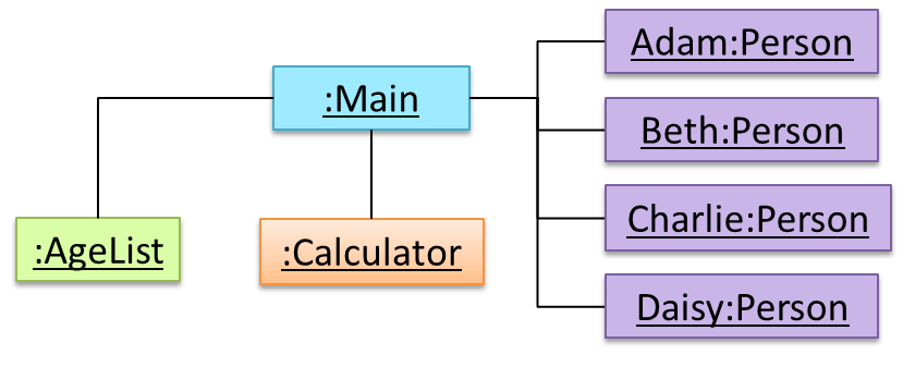
📦 Classes and objects in an example scenario
When writing an OOP program to calculate the average age of Adam, Beth, Charlie, and Daisy, instructions for creating objects Adam, Beth, Charlie, and Daisy will be very similar because they
are all of the same kind : they all represent ‘persons’ with the same interface, the same kind of data (i.e. name, DoB, etc.), and the same kind of behavior (i.e. getAge(Date), getName(),
etc.). Therefore, we can have a class called Person containing instructions on how to create Person objects and use that class to instantiate objects Adam, Beth, Charlie, and
Daisy. Similarly, we need classes AgeList, Calculator, and Main classes to instantiate one each of AgeList, Calculator, and Main objects.
Let us use the UML notation to illustrate classes and objects under discussion.
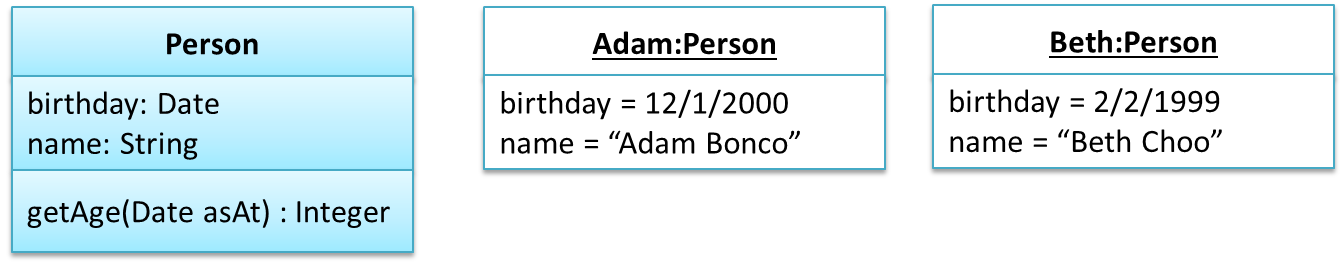
Person class and some example instances of the Person class.
Class Level Members
While all objects of a class has the same attributes, each object has its own copy of the attribute value.
Example:
All Person objects have the Name attribute but the value of that attribute varies between Person objects.
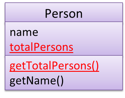
However, some attributes are not suitable to be maintained by individual objects. Instead, they should be maintained centrally, shared by all objects of the class. They are like ‘global variables’ but attached to a specific class. Such variables whose value is shared by all instances of a class are called class level attributes.
Example:
The attribute totalPersons should be maintained centrally and shared by all Person objects rather than copied at each Person object.
Similarly, when a normal method is being called, a message is being sent to the receiving object and the result may depend on the receiving object.
Example:
Sending the getName() message to Adam object results in the response "Adam" while sending the same message to the Beth object gets the response "Beth".
However, there can be methods related to a specific class but not suitable for sending message to a specific object of that class. Such methods that are called using the class instead of a specific instance are called class-level methods.
Example:
The method getTotalPersons() is not suitable to send to a specific Person object because a specific object of the Person class should not know about the total number of Person objects.
Class-level attributes and methods are collectively called class-level members (also called static members sometimes because some programming languages use the keyword static to identify
class-level members). They are to be accessed using the class name rather than an instance of the class.
📦 A Student class with a class-level attribute and a method:
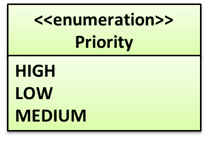
Enumerations
An Enumeration is a fixed set of values that can be considered as a data type.
An enumeration is often useful when using a regular data type such as int or String would allow invalid values to be assigned to a variable. e.g. if a variable can only take values 0 and 1, declaring it as an int would allow invalid values such as 2 to be assigned to it. But if you define an enumeration called Binary that has values 0 and 1 only, a variable of type Binary will never be assigned an invalid value such as 2 because the compiler is able to catch the error.
📦 Priority can be considered an enumeration because it has only three values.
Priority: HIGH, MEDIUM, LOW
Associations
Basic
Objects in an OO solution need to be connected to each other to form a network so that they can interact with each other. Such connections between objects are called associations.
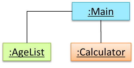
📦 An object diagram example showing associations among objects. For example, there is an association between the AgeList object and the Main object.
Associations in an object structure can change over time.
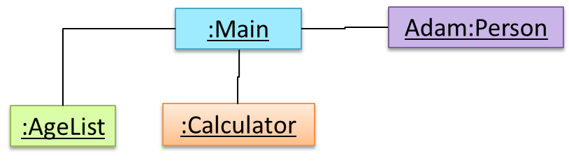
📦 In this example, the associations in the object structure have changed (from left to right) due to a new Person object being connected to the Main object.
 →
→
Associations among objects are reflected correspondingly in the class diagram too, as it is the class diagram that dictates the nature of the associations allowed in the object structures.
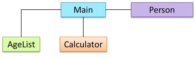
📦 An example class diagram showing associations between classes.
Navigability
When two classes are linked by an association, it does not necessarily mean both classes know about each other. The concept of which class in the association knows about the other class is called navigability.
Multiplicity
Multiplicity is the aspect of an OOP solution that dictates how many objects take part in each association.
📦 This class diagram does not tell us multiplicities. For exaple, how many Calculator objects can be associated with one Main object? How many Main objects can be associated with one Calculator object? and so on.
Dependencies
Dependencies are objects that are not directly linked in the object network can still interact with each other. These are a weaker form of associations we call dependencies.
Composition
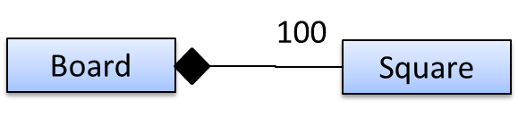
A composition is an association that represents a strong whole-part relationship. When the whole is destroyed, parts are destroyed too.
📦 A Board (used for playing board games) consists of Square objects.
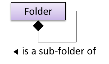
Composition also implies that there cannot be cyclical links.
📦 In this ‘sub-folder’ association, a Folder cannot be a sub-folder of itself. If the diamond is removed, it is no longer a composition relationship and technically, allows a folder to be sub-folder of itself.
Aggregation 
Aggregation represents a container-contained relationship. It is a weaker relationship than composition.
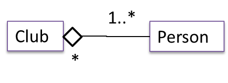
📦 Club acts as a container for Person objects. Person objects can survive without a Club object.
Aggregation vs Composition
The distinction between composition (◆) and aggregation (◇) is rather blurred. Martin Fowler’s famous book UML Distilled advocates omitting the aggregation symbol altogether because using it adds more confusion than clarity.
Association Classes
An association class represents additional information about an association. It is a normal class but plays a special role from a design point of view.
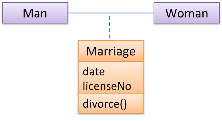
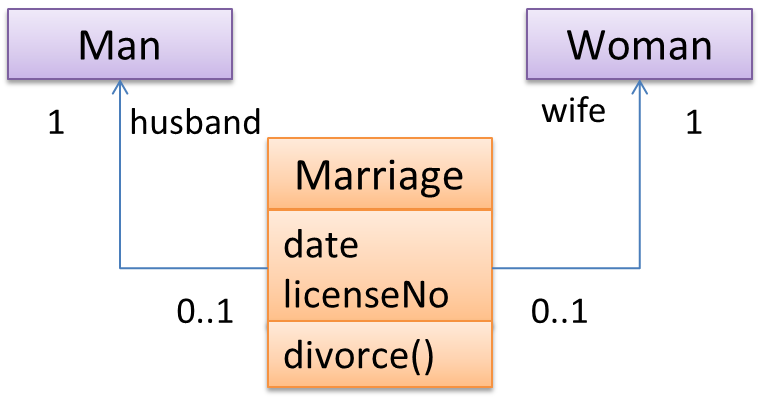
📦 A Man class and a Woman class is linked with a ‘married to’ association and there is a need to store the date of marriage. However, that data is related to the association rather than specifically owned by either
the Man object or the Woman object. In such situations, an additional association class can be introduced, e.g. a Marriage class, to store such information.
Inheritance
What
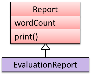
The OOP concept Inheritance allows you to define a new class based on an existing class. For example, you can use inheritance to define an EvaluationReport class based on an existing Report class so that the EvaluationReport class does not have to duplicate code that is already implemented in the Report class.
📦 Example: The EvaluationReport inherits the wordCount attribute and the print() method from the base class Report.
- Other names for Base class: Parent class, Super class
- Other names for Derived class: Child class, Sub class, Extended class
A super class is said to be more general than the sub class. Conversely, a sub class is said to be more specialized than the super class.
Applying inheritance on a group of similar classes can result in the common parts among classes being extracted into more general classes.
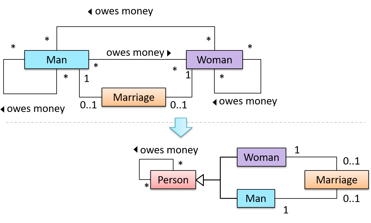
📦 Man and Woman behaves the same way for the 'owes money' association. However, the two classes cannot be simply replaced with a more general class Person because of the need to distinguish between Man and Woman for the ‘marriage’ association. A solution is to add the Person class as a super class and let Man and Woman inherit from Person.
Inheritance implies the derived class can be considered as a sub-type of the base class (and the base class is a super-type of the derived class), resulting in an is a relationship.
Inheritance does not necessarily mean a sub-type relationship exists. However, the two often go hand-in-hand. For simplicity, at this point let us assume inheritance implies a sub-type relationship.
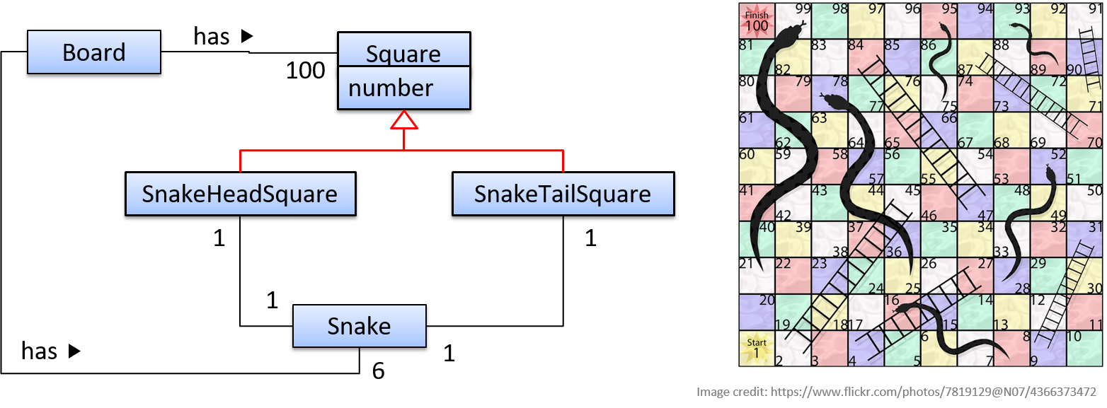
📦 In this class diagrams of a Snakes and Ladders board game,
SnakeHeadSquareis aSquare(aSnakeHeadSquareis a square in which the head of a snake appears)SnakeTailSquareis aSquare
Inheritance relationships through a chain of classes can result in inheritance hierarchies (aka inheritance trees).
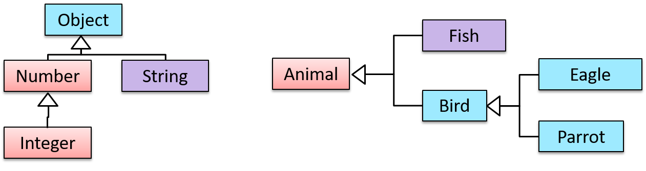
📦 Two inheritance hierarchies/trees are given below. Note that Parrot is a Bird as well as it is an Animal.
Multiple Inheritance is when a class inherits directly from multiple classes. Multiple inheritance is allowed among C++ classes but not among Java classes.
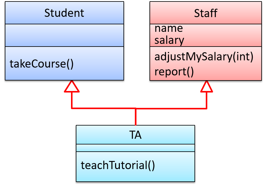
📦 The TA class inherits from the Staff class and the Student.
Overriding
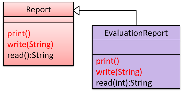
Method overriding is when a sub-class changes the behavior inherited from the parent class by re-implementing the method. Overridden methods have the same name, same type signature, and same return type.
📦 In the diagram below,
Report#print()method is overridden byEvaluationReport#print()method.Report#write(String)method is overridden byEvaluationReport#write(String)method.Report#read():Stringmethod is NOT overridden byEvaluationReport#read(int):Stringmethod. Reason: the two methods have different signatures;EvaluationReport#read(int):Stringoverloads (rather than overrides) theReport#read():Stringmethod.
Design → Object Oriented Programming →
Overloading
Method overloading is when there are multiple methods with the same name but different type signatures. Overloading is used to indicate that multiple operations do similar things but take different parameters.
Type Signature: The type signature of an operation is the type sequence of the parameters. The return type and parameter names are not part of the type signature. However, the parameter order is significant.
| Method | Type Signature |
|---|---|
int add(int X, int Y) |
(int, int) |
void add(int A, int B) |
(int, int) |
void m(int X, double Y) |
(int, double) |
void m(double X, int Y) |
(double, int) |
📦 In the class below, the calculate method is overloaded because the two methods have the same name but different type signatures (String) and (int[])
class RatingCalculator{
    void calculate(String matric) { ... }
    void calculate(int[] averages) { ... }
}
Interfaces
An interface is a behavior specification i.e. a collection of
There are a number of situations in software engineering when it is important for disparate groups of programmers to agree to a "contract" that spells out how their software interacts. Each group should be able to write their code without any knowledge of how the other group's code is written. Generally speaking, interfaces are such contracts. --Oracle Docs on Java
📦 SalariedStaff is an interface that contains two methods setSalary(int) and getSalary(). AcademicStaff implements the SalariedStaff interface. That means an AcademicStaff object is able to support the behaviors setSalary(int) and getSalary(). That's why the same two methods also appear under the methods implemented by the AcademicStaff class (in blue)
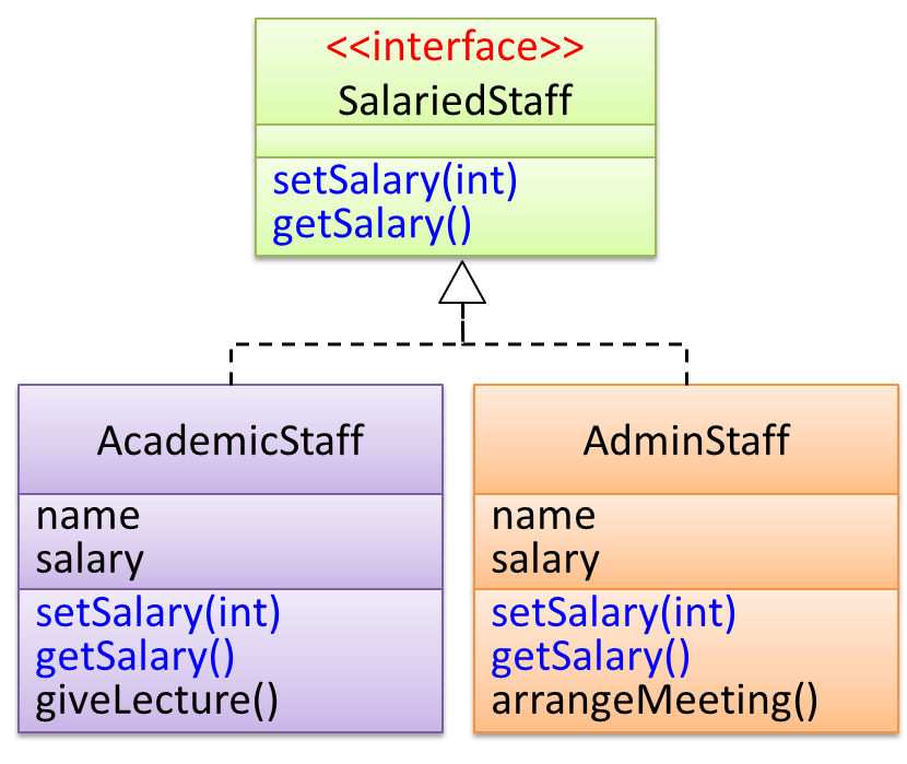
A class implementing an interface results in an is-a relationship, just like in class inheritance.
📦 In the example above, AcademicStaff is a SalariedStaff. An AcademicStaff object can be used anywhere a SalariedStaff object is expected e.g. SalariedStaff ss = new AcademicStaff().
Similarly, AdminStaff is a SalariedStaff too.
Abstract Classes
Abstract Class:
An abstract class is a class that is declared abstract—it may or may not include abstract methods. Abstract classes cannot be instantiated, but they can be subclassed. -- Oracle's Java Documentation
An abstract method is simply the method interface without the implementation.
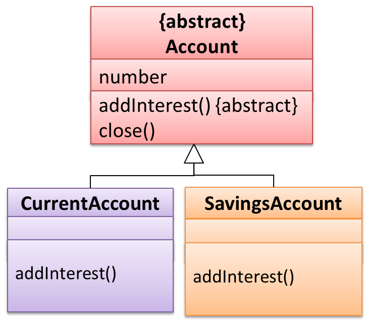
📦 The Account class has an abstract method (addInterest()).
Dynamic and Static Binding
Dynamic Binding (
Implementation → Object Oriented Programming →
Implementing Overriding
To override a method inherited from an ancestor class, simply re-implement the method in the target class.
📦 A simple example where the Report#print() method is overridden by EvaluationReport#print() method:
class Report{

    void print(){
        System.out.println("Printing report");
    }

}

class EvaluationReport extends Report{

    @Override  // this annotation is optional
    void print(){
        System.out.println("Printing evaluation report");
    }

}

class ReportMain{

    public static void main(String[] args){
        Report report = new Report();
        report.print(); // prints "Printing report"

        EvaluationReport evaluationReport = new EvaluationReport();
        evaluationReport.print(); // prints "Printing evaluation report"
    }
}
- Java - Overriding -- a tutorial by tutorialspoint.com
Which of these methods override another method?
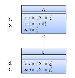
- a
- b
- c
- d
- e
d
Explanation: Method overriding requires a method in a child class to use the same method name and same parameter sequence used by one of its ancestors
📦 Consider the code below. The declared type of s is Staff and it appears as if the adjustSalary(int) operation of the Staff class is invoked.
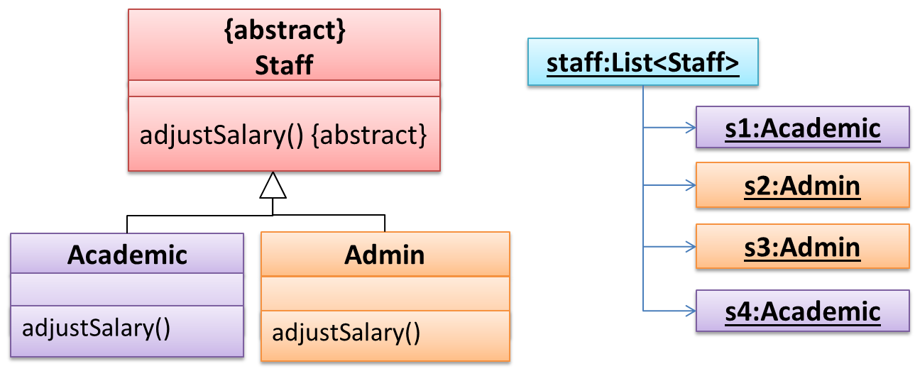
void adjustSalary(int byPercent) {
    for (Staff s: staff) {
        s.adjustSalary(byPercent);
    }
}
However, at runtime the adjustSalary(int) operation of the actual object will be called (i.e. adjustSalary(int) operation of Admin or Academic). If the actual object does not override that
operation, the operation defined in the immediate superclass (in this case, Staff class) will be called.
Static binding (aka early binding): When a method call is resolved at compile time.
In contrast,
Implementation → Object Oriented Programming →
Implementing Overloading
An operation can be overloaded inside the same class or in sub/super classes.
📦 The constructor of the Account class below is overloaded because there are two constructors with different signatures: () and (String, String, double). Furthermore, the save method in the Account class is overloaded in the child class SavingAccount.
class Account {
    Account () {
        ...
    }

    Account (String name, String number, double balance) {
        ...
    }

    void save(int amount){
        ...
    }
}

class SavingAccount extends Account{

    void save(Double amount){
        ...
    }
}
- Method Overloading in Java a tutorial from javatpoint.com. Also mentions the topic of a related topic type promotion.
📦 Note how the constructor is overloaded in the class below. The method call new Account() is bound to the first constructor at compile time.
class Account {
    Account () {
        // Signature: ()
        ...
    }
    Account (String name, String number, double balance) {
        // Signature: (String, String, double)
        ...
    }
}
📦 Similarly, the calcuateGrade method is overloaded in the code below and a method call calculateGrade("A1213232") is bound to the second implementation, at compile time.
void calculateGrade (int[] averages) { ... }
void calculateGrade (String matric) { ... }
Substitutability
Every instance of a subclass is an instance of the superclass, but not vice-versa. As a result, inheritance allows substitutability : the ability to substitute a child class object where a parent class object is expected.
📦 an Academic is an instance of a Staff, but a Staff is not necessarily an instance of an Academic. i.e. wherever an object of the superclass is expected, it can be substituted by an object
of any of its subclasses.
The following code is valid because an AcademicStaff object is substitutable as a Staff object.
Staff staff = new AcademicStaff (); // OK
But the following code is not valid because staff is declared as a Staff type and therefore its value may or may not be of type AcademicStaff, which is the type expected by variable academicStaff.
Staff staff;
...
AcademicStaff academicStaff = staff; // Not OK
Polymorphism
Introduction
Polymorphism:
The ability of different objects to respond, each in its own way, to identical messages is called polymorphism. -- Object-Oriented Programming with Objective-C, Apple
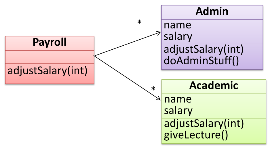
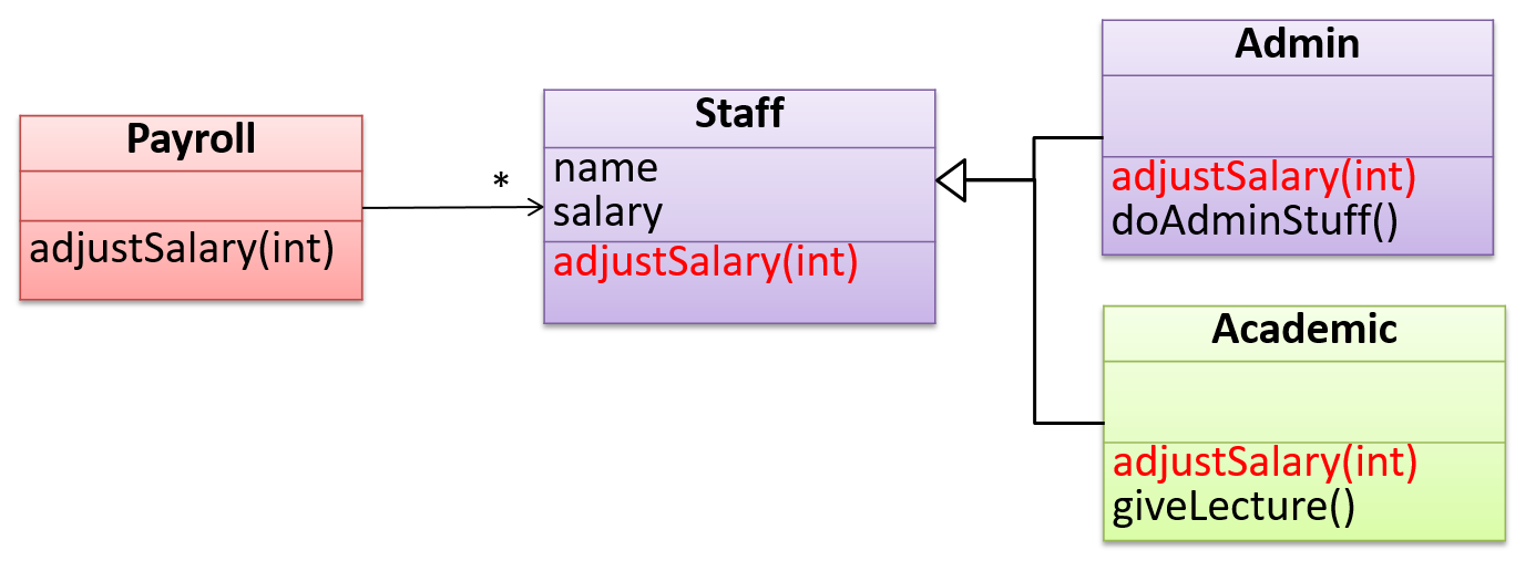
Take the example of writing a payroll application for a university to facilitate payroll processing of university staff. Suppose an adjustSalary(int) operation adjusts the salaries of all staff members. This operation will be executed
whenever the university initiates a salary adjustment for its staff. However, the adjustment formula is different for different staff categories, say admin and academic. Here is one possible way of designing the classes in the Payroll system.
📦 Calling adjustSalary() method for each Staff type:
Here is the implementation of the adjustSalary(int) operation from the above design.
class Payroll1 {
    ArrayList< Admin > admins;
    ArrayList< Academic > academics;
    // ...

    void adjustSalary(int byPercent) {
        for (Admin ad: admins) {
            ad.adjustSalary(byPercent);
        }
        for (Academic ac: academics) {
            ac.adjustSalary(byPercent);
        }
    }
}
Note how processing is similar for the two staff types. It is as if the type of staff members is irrelevant to how they are processed inside this operation! If that is the case, can the staff type be "abstracted away" from this method?
Here is such an implementation of adjustSalary(int):
class Payroll2 {
    ArrayList< Staff > staff;
    // ...

    void adjustSalary(int byPercent) {
        for (Staff s: staff) {
            s.adjustSalary(byPercent);
        }
    }
}
Notice the following:
- Only one data structure
ArrayList< Staff >. It contains bothAdminandAcademicobjects but treats them asStaffobjects - Only one loop
- Outcome of the
s.adjustSalary(byPercent)method call depends on whethersis anAcademicorAdminobject
The above code is better in several ways:
- It is shorter.
- It is simpler.
- It is more flexible (this code will remain the same even if more staff types are added).
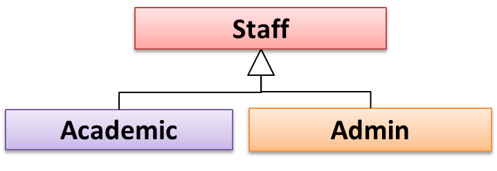
This does not mean we are getting rid of the Academic and Admin classes completely and replacing them with a more general class called Staff. Rather, this part of the code “treats” both Admin and Academic objects as one type called Staff.
For example, ArrayList staff contains both Admin and Academic objects although it treats all of them as Staff objects. However, when the adjustSalary(int) operation of these objects
is called, the resulting salary adjustment will be different for Admin objects and Academic objects. Therefore, different types of objects are treated as a single general type, but yet each type of object exhibits
a different kind of behavior. This is called polymorphism (literally, it means “ability to take many forms”). In this example, an object that is perceived as type Staff can be an Admin object or an Academic object.
Mechanism
Three concepts combine to achieve polymorphism: substitutability, operation overriding, and dynamic binding.
- Substitutability: Because of substitutability, you can write code that expects object of a parent class and yet use that code with objects of child classes. That is how polymorphism is able to treat objects of different types as one type.
- Overriding: To get polymorphic behavior from an operation, the operation in the superclass needs to be overridden in each of the subclasses. That is how overriding allows objects of different sub classes to display different behaviors in response to the same method call.
- Dynamic binding: Calls to overridden methods are bound to the implementation of the actual object's class dynamically during the runtime. That is how the polymorphic code can call the method of the parent class and yet execute the implementation of the child class.
Miscellaneous
Miscellaneous
What’s the difference between a Class, an Abstract Class, and an Interface? ![]()
- An interface is a behavior specification with no implementation.
- A class is a behavior specification + implementation.
- An abstract class is a behavior specification + a possibly incomplete implementation.
How does overriding differ from overloading? ![]()
Overloading is used to indicate that multiple operations do similar things but take different parameters. Overloaded methods have the same method name but different method signatures and possibly different return types.
Overriding is when a sub-class redefines an operation using the same method name and the same type signature. Overridden methods have the same name, same method signature, and same return type.
OOP - Implementation
Implementing Classes
Given below is a tutorial you can refer to (from Oracle’s official Java tutorials) to learn how to implement java classes, in the unlikely case you don't know how to do that already.
- Classes, methods, variables – Start from the linked page and follow the next few steps in the tutorial
Implementing Class-Level Members
You can refer to Oracle’s official Java tutorial on class-level members to learn how to implement Java class-level members, in the unlikely case you don't know how to do that already.
Implementing Associations
We use instance level variables to implement associations.
A normal instance-level variable gives us a 0..1 multiplicity (also called optional associations) because a variable can hold a reference to a single object or null.
class Logic {
    Minefield minefield;
    ...
}
class Minefield {
    ...
}
A variable can be used to implement a 1 multiplicity too (also called compulsory associations).
class Logic {
    ConfigGenerator cg = new ConfigGenerator();
    ...
}
Bi-directional associations require matching variables in both classes.
class Foo {
    Bar bar;
    ...
}
class Bar {
    Foo foo;
    ...
}
To implement other multiplicities, choose a suitable data structure such as Arrays, ArrayLists, HashMaps, Sets, etc.
class Minefield {
    Cell[][] cell;
    ...
}
Implementing Dependencies
Dependencies result from interactions between objects that do not result in a long-term link between the said objects.
Example:
class TaxProcessor{
    double rate;

    void addTax(Taxable t){
        t.addTax(rate);
    }
}
The code above results in this dependency.
The code does not indicate an association between the two classes because the TaxProcessor object does not keep the Taxable object (i.e. it’s only a short-term interaction)
Implementing Composition
Composition too is implemented using a normal variable. If correctly implemented, the ‘part’ object will be deleted when the ‘whole’ object is deleted. Ideally, the ‘part’ object may not even be visible to clients of the ‘whole’ object.
Example:
class Car {
    private Engine engine;
  ...
}
Implementing Aggregation
Implementation is similar to that of composition except the containee object can exist even after the container object is deleted.
📦 Example:
class Car {
    Person driver;
    ...
    void drive(Person p) {
        driver = p;
    }
}
Implementing Association Classes
Note that while a special notation is used to indicate an association class, there is no special way to implement an association class.
Example:

At implementation level, an association class is most likely implemented as follows.
Implementing Inheritance
To learn how to implement inheritance in Java, you can follow [Oracle’s Java Tutorials: Inheritance]
A very beginner-friendly video about implementing Java inheritance.
Java requires all class to have a parent class. If you do not specify a parent class, Java automatically assigns the Object class as the parent class.
Implementing Overriding
To override a method inherited from an ancestor class, simply re-implement the method in the target class.
📦 A simple example where the Report#print() method is overridden by EvaluationReport#print() method:
class Report{

    void print(){
        System.out.println("Printing report");
    }

}

class EvaluationReport extends Report{

    @Override  // this annotation is optional
    void print(){
        System.out.println("Printing evaluation report");
    }

}

class ReportMain{

    public static void main(String[] args){
        Report report = new Report();
        report.print(); // prints "Printing report"

        EvaluationReport evaluationReport = new EvaluationReport();
        evaluationReport.print(); // prints "Printing evaluation report"
    }
}
Implementing Overloading
An operation can be overloaded inside the same class or in sub/super classes.
📦 The constructor of the Account class below is overloaded because there are two constructors with different signatures: () and (String, String, double). Furthermore, the save method
in the Account class is overloaded in the child class SavingAccount.
class Account {
    Account () {
        ...
    }

    Account (String name, String number, double balance) {
        ...
    }

    void save(int amount){
        ...
    }
}

class SavingAccount extends Account{

    void save(Double amount){
        ...
    }
}
Implementing Interfaces
Java allows multiple inheritance among interfaces. A Java class can implement multiple interfaces (and inherit from one class).
📦 The design below is allowed by Java.
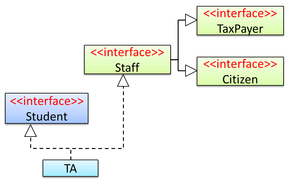
Staffinterface inherits (note the solid lines) the interfacesTaxPayerandCitizen.TAclass implements bothStudentinterface and theStaffinterface.- Because of point 1 above,
TAclass has to implement all methods in the interfacesTaxPayerandCitizen. - Because of points 1,2,3, a
TAis aStaff, is aTaxPayerand is aCitizen.
Java uses the interface keyword to declare interfaces and implements keyword to indicate that a class implements a given interface. Inheritance among interfaces uses the extends keyword,
just like inheritance among classes.
📦 The code for the example design given in the previous example:
interface TaxPayer {
    void payTax();
}

interface Citizen {
    void vote();
}

interface Staff extends Citizen, TaxPayer{
    void work();
}

interface Student {
    void learn();
}

class TA implements Student, Staff{

    @Override
    public void payTax() {
        //...
    }

    @Override
    public void vote() {
        //...
    }

    @Override
    public void work() {
        //...
    }

    @Override
    public void learn() {
        //...
    }
}
Implementing Abstract Classes
Use the abstract keyword to identify abstract classes/methods.
📦 Partial code below gives an example of how to declare abstract classes/methods.
abstract class Account {

    int number;

    abstract void addInterest();

    void close(){
        //...
    }
}

class CurrentAccount extends Account{

    @Override
    void addInterest() {
        //...
    }
}
In Java, if a class contains an abstract method, the class itself should be an abstract class i.e. if any methods of the class is 'incomplete', the class itself is 'incomplete'.
Implementing Polymorphism
We can use inheritance to achieve polymorphism.
📦 Continuing with the example given in [
Staff, Admin, and Academic classes that achieves the desired polymorphism.
Design → Object Oriented Programming → Polymorphism →
Introduction
Polymorphism:
The ability of different objects to respond, each in its own way, to identical messages is called polymorphism. -- Object-Oriented Programming with Objective-C, Apple
Take the example of writing a payroll application for a university to facilitate payroll processing of university staff. Suppose an adjustSalary(int) operation adjusts the salaries of all staff members. This operation
will be executed whenever the university initiates a salary adjustment for its staff. However, the adjustment formula is different for different staff categories, say admin and academic. Here is one possible way of designing the
classes in the Payroll system.
📦 Calling adjustSalary() method for each Staff type:
Here is the implementation of the adjustSalary(int) operation from the above design.
class Payroll1 {
    ArrayList< Admin > admins;
    ArrayList< Academic > academics;
    // ...

    void adjustSalary(int byPercent) {
        for (Admin ad: admins) {
            ad.adjustSalary(byPercent);
        }
        for (Academic ac: academics) {
            ac.adjustSalary(byPercent);
        }
    }
}
Note how processing is similar for the two staff types. It is as if the type of staff members is irrelevant to how they are processed inside this operation! If that is the case, can the staff type be "abstracted away" from
this method? Here is such an implementation of adjustSalary(int):
class Payroll2 {
    ArrayList< Staff > staff;
    // ...

    void adjustSalary(int byPercent) {
        for (Staff s: staff) {
            s.adjustSalary(byPercent);
        }
    }
}
Notice the following:
- Only one data structure
ArrayList< Staff >. It contains bothAdminandAcademicobjects but treats them asStaffobjects - Only one loop
- Outcome of the
s.adjustSalary(byPercent)method call depends on whethersis anAcademicorAdminobject
The above code is better in several ways:
- It is shorter.
- It is simpler.
- It is more flexible (this code will remain the same even if more staff types are added).
This does not mean we are getting rid of the Academic and Admin classes completely and replacing them with a more general class called Staff. Rather, this part of the code “treats” both Admin and Academic objects as one type called Staff.
For example, ArrayList staff contains both Admin and Academic objects although it treats all of them as Staff objects. However, when the adjustSalary(int) operation of
these objects is called, the resulting salary adjustment will be different for Admin objects and Academic objects. Therefore, different types of objects are treated as a single general type, but yet each
type of object exhibits a different kind of behavior. This is called polymorphism (literally, it means “ability to take many forms”). In this example, an object that is perceived as type Staff can be an Admin object or an Academic object.
class Staff {
    String name;
    double salary;

    void adjustSalary(int percent) {
        // do nothing
    }
}

//------------------------------------------

class Admin extends Staff {

    @Override
    void adjustSalary(int percent) {
        salary = salary * percent;
    }
}

//------------------------------------------

class Academic extends Staff {

    @Override
    void adjustSalary(int percent) {
        salary = salary * percent * 2;
    }
}

//------------------------------------------

class Payroll {
    ArrayList< Staff > staff;
    // ...

    void adjustSalary(int byPercent) {
        for (Staff s: staff) {
            s.adjustSalary(byPercent);
        }
    }
}
SECTION: REQUIREMENTS
Requirements
Introduction
A software requirement specifies a need to be fulfilled by the software product.
A software project may be,
- a brown-field project i.e., develop a product to replace/update an existing software product
- a green-field project i.e., develop a totally new system with no precedent
In either case, requirements need to be gathered, analyzed, specified, and managed.
Requirements come from stakeholders.
Stakeholder: A party that is potentially affected by the software project. e.g. users, sponsors, developers, interest groups, government agencies, etc.
Identifying requirements is often not easy. For example, stakeholders may not be aware of their precise needs, may not know how to communicate their requirements correctly, may not be willing to spend effort in identifying requirements, etc.
Non-Functional Requirements
There are two kinds of requirements:
- Functional requirements specify what the system should do.
- Non-functional requirements specify the constraints under which system is developed and operated.
📦 Some examples of non-functional requirement categories:
- Data requirements e.g. size,
volatility ,persistency etc., - Environment requirements e.g. technical environment in which system would operate or need to be compatible with.
- Accessibility, Capacity, Compliance with regulations, Documentation, Disaster recovery, Efficiency, Extensibility, Fault tolerance, Interoperability, Maintainability, Privacy, Portability, Quality, Reliability, Response time, Robustness, Scalability, Security, Stability, Testability, and more ...
- Business/domain rules: e.g. the size of the minefield cannot be smaller than five.
- Constraints: e.g. the system should be backward compatible with data produced by earlier versions of the system; system testers are available only during the last month of the project; the total project cost should not exceed $1.5 million.
- Technical requirements: e.g. the system should work on both 32-bit and 64-bit environments.
- Performance requirements: e.g. the system should respond within two seconds.
- Quality requirements: e.g. the system should be usable by a novice who has never carried out an online purchase.
- Process requirements: e.g. the project is expected to adhere to a schedule that delivers a feature set every one month.
- Notes about project scope: e.g. the product is not required to handle the printing of reports.
- Any other noteworthy points: e.g. the game should not use images deemed offensive to those injured in real mine clearing activities.
We should spend extra effort in digging NFRs out as early as possible because NFRs are easier to miss e.g., stakeholders tend to think of functional requirements first and sometimes they are critical to the success of the software. E.g. A web application that is too slow or that has low security is unlikely to succeed even if it has all the right functionality.
Prioritizing Requirements
Requirements can be prioritized based the importance and urgency, while keeping in mind the constraints of schedule, budget, staff resources, quality goals, and other constraints.
A common approach is to group requirements into priority categories. Note that all such scales are subjective, and stakeholders define the meaning of each level in the scale for the project at hand.
📦 An example scheme for categorizing requirements:
Essential: The product must have this requirement fulfilled or else it does not get user acceptanceTypical: Most similar systems have this feature although the product can survive without it.Novel: New features that could differentiate this product from the rest.
📦 Other schemes:
High,Medium,LowMust-have,Nice-to-have,Unlikely-to-haveLevel 0,Level 1,Level 2, ...
Some requirements can be discarded if they are considered ‘out of
📦 The requirement given below is for a Calendar application. Stakeholder of the software (e.g. product designers) might decide the following requirement is not in the scope of the software.
The software records the actual time taken by each task and show the difference between the actual and scheduled time for the task.
Quality of Requirements
Here are some characteristics of well-defined requirements
- Unambiguous
- Testable (verifiable)
- Clear (concise, terse, simple, precise)
- Correct
- Understandable
- Feasible (realistic, possible)
- Independent
-
Atomic - Necessary
- Implementation-free (i.e. abstract)
Besides these criteria for individual requirements, the set of requirements as a whole should be
- Consistent
- Non-redundant
- Complete
Peter Zielczynski, Requirements Management Using IBM Rational RequisitePro, IBM Press, 2008
Gathering Requirements
Brainstorming
Brainstorming: A group activity designed to generate a large number of diverse and creative ideas for the solution of a problem.
In a brainstorming session there are no "bad" ideas. The aim is to generate ideas; not to validate them. Brainstorming encourages you to "think outside the box" and put "crazy" ideas on the table without fear of rejection.
User Surveys
Surveys can be used to solicit responses and opinions from a large number of stakeholders regarding a current product or a new product.
Observation
Observing users in their natural work environment can uncover product requirements. Usage data of an existing system can also be used to gather information about how an existing system is being used, which can help in building a better replacement e.g. to find the situations where the user makes mistakes when using the current system.
Interviews
Interviewing stakeholders and
Domain Expert : An expert of a discipline to which the product is connected e.g., for a software used for Accounting, a domain expert is someone who is an expert of Accounting.
Focus Groups

[source]
Focus groups are a kind of informal interview within an interactive group setting. A group of people (e.g. potential users, beta testers) are asked about their understanding of a specific issue, process, product, advertisement, etc.
Prototyping
Prototype: A prototype is a mock up, a scaled down version, or a partial system constructed
- to get users’ feedback.
- to validate a technical concept (a "proof-of-concept" prototype).
- to give a preview of what is to come, or to compare multiple alternatives on a small scale before committing fully to one alternative.
- for early field-testing under controlled conditions.
Prototyping can uncover requirements, in particular, those related to how users interact with the system. UI prototypes are often used in brainstorming sessions, or in meetings with the users to get quick feedback from them.

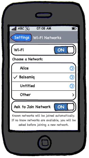
[source: http://balsamiq.com/products/mockups]
💡 Prototyping can be used for discovering as well as specifying requirements e.g. a UI prototype can serve as a specification of what to build.
Product Surveys
Studying existing products can unearth shortcomings of existing solutions that can be addressed by a new product. Product manuals and other forms of technical documentation of an existing system can be a good way to learn about how the existing solutions work.
📦 When developing a game for a mobile device, a look at a similar PC game can give insight into the kind of features and interactions the mobile game can offer.
Specifying Requirements
Prose
What
A normal textual description (i.e. prose) can be used to describe requirements. Prose is especially useful when describing abstract ideas such as the vision of a product.
📦 The product vision of the TEAMMATES Project given below is described using prose.
TEAMMATES aims to become the biggest student project in the world (biggest here refers to 'many contributors, many users, large code base, evolving over a long period'). Furthermore, it aims to serve as a training tool for Software Engineering students who want to learn SE skills in the context of a non-trivial real software product.
❗️ Avoid using lengthy prose to describe requirements; they can be hard to follow.
Feature List
What
Feature List: A list of features of a product grouped according to some criteria such as aspect, priority, order of delivery, etc.
📦 A sample feature list from a simple Minesweeper game (only a brief description has been provided to save space):
- Basic play – Single player play.
- Difficulty levels
- Medium-levels
- Advanced levels
- Versus play – Two players can play against each other.
- Timer – Additional fixed time restriction on the player.
- ...
User Stories
Introduction
User story: User stories are short, simple descriptions of a feature told from the perspective of the person who desires the new capability, usually a user or customer of the system. [Mike Cohn]
A common format for writing user stories is:
User story format: As a {user type/role} I can {function} so that {benefit}
📦 Examples (from a Learning Management System):
- As a student, I can download files uploaded by lecturers, so that I can get my own copy of the files
- As a lecturer, I can create discussion forums, so that students can discuss things online
- As a tutor, I can print attendance sheets, so that I can take attendance during the class
We can write user stories on index cards or sticky notes, and arrange on walls or tables, to facilitate planning and discussion. Alternatively, we can use a software (e.g., GitHub Project Boards, Trello, Google Docs, ...) to manage user stories digitally.


[credit: https://www.flickr.com/photos/jakuza/with/2726048607/]
[credit: https://commons.wikimedia.org/wiki/File:User_Story_Map_in_Action.png]
Details
The {benefit} can be omitted if it is obvious.
As a user, I can login to the system so that I can access my data
❗️ It is recommended to confirm there is a concrete benefit even if you omit it from the user story. If not, we could end up adding features that have no real benefit.
We can add more characteristics to the {user role} to provide more context to the user story.
- As a forgetful user, I can view a password hint, so that I can recall my password.
- As an expert user, I can tweak the underlying formatting tags of the document, so that I can format the document exactly as I need.
We can write user stories at various levels. High-level user stories, called epics (or themes) cover bigger functionality. We can then break down these epics to multiple user stories of normal size.
[Epic] As a lecturer, I can monitor student participation levels
- As a lecturer, I can view the forum post count of each student so that I can identify the activity level of students in the forum
- As a lecturer, I can view webcast view records of each student so that I can identify the students who did not view webcasts
- As a lecturer, I can view file download statistics of each student so that I can identify the students who do not download lecture materials
We can add conditions of satisfaction to a user story to specify things that need to be true for the user story implementation to be accepted as ‘done’.
- As a lecturer, I can view the forum post count of each student so that I can identify the activity level of students in the forum.
Conditions:
- Separate post count for each forum should be shown
- Total post count of a student should be shown
- The list should be sortable by student name and post count
Other useful info that can be added to a user story includes (but not limited to)
- Priority: how important the user story is
- Size: the estimated effort to implement the user story
- Urgency: how soon the feature is needed
User stories for a travel website (credit: Mike Cohen)
- As a registered user, I am required to log in so that I can access the system
- As a forgetful user, I can request a password reminder so that I can log in if I forget mine
- [Epic] As a user, I can cancel a reservation
- As a premium site member, I can cancel a reservation up to the last minute
- As a non-premium member, I can cancel up to 24 hours in advance
- As a member, I am emailed a confirmation of any cancelled reservation
- [Epic] As a frequent flyer, I want to book a trip
- As a frequent flyer, I want to book a trip using miles
- As a frequent flyer, I want to rebook a trip I take often
- As a frequent flyer, I want to request an upgrade
- As a frequent flyer, I want to see if my upgrade cleared
Usage
User stories capture user requirements in a way that is convenient for
[User stories] strongly shift the focus from writing about features to discussing them. In fact, these discussions are more important than whatever text is written. [Mike Cohn, MountainGoat Software 🔗]
User stories differ from
User stories can capture non-functional requirements too because even NFRs must benefit some stakeholder.
📦 An example of a NFR captured as a user story:
| As a | I want to | so that |
|---|---|---|
| impatient user | to be able experience reasonable response time from the website while up to 1000 concurrent users are using it | I can use the app even when the traffic is at the maximum expected level |
Given their lightweight nature, user stories are quite handy for recording requirements during early requirements gathering.
💡 Here are some tips for using user stories for early stages of requirement gathering:
- Define the target user:
Decide your target user's profile (e.g. a student, office worker, programmer, sales person) and work patterns (e.g. Does he work in groups or alone? Does he share his computer with others?). A clear understanding of the target user will help when deciding the importance of a user story. You can even give this user a name. e.g. Target user Jean is a university student studying in a non-IT field. She interacts with a lot of people due to her involvement in university clubs/societies. ... - Define the problem scope: Decide that exact problem you are going to solve for the target user. e.g. Help Jean keep track of all her school contacts
- Don't be too hasty to discard 'unusual' user stories:
Those might make your product unique and stand out from the rest, at least for the target users. - Don't go into too much details:
For example, consider this user story:As a user, I want to see a list of tasks that needs my attention most at the present time, so that I pay attention to them first.
When discussing this user story, don't worry about what tasks should be considered needs my attention most at the present time. Those details can be worked out later. - Don't be biased by preconceived product ideas:
When you are at the stage of identifying user needs, clear your mind of ideas you have about what your end product will look like. - Don't discuss implementation details or whether you are actually going to implement it:
When gathering requirements, your decision is whether the user's need is important enough for you to want to fulfil it. Implementation details can be discussed later. If a user story turns out to be too difficult to implement later, you can always omit it from the implementation plan.
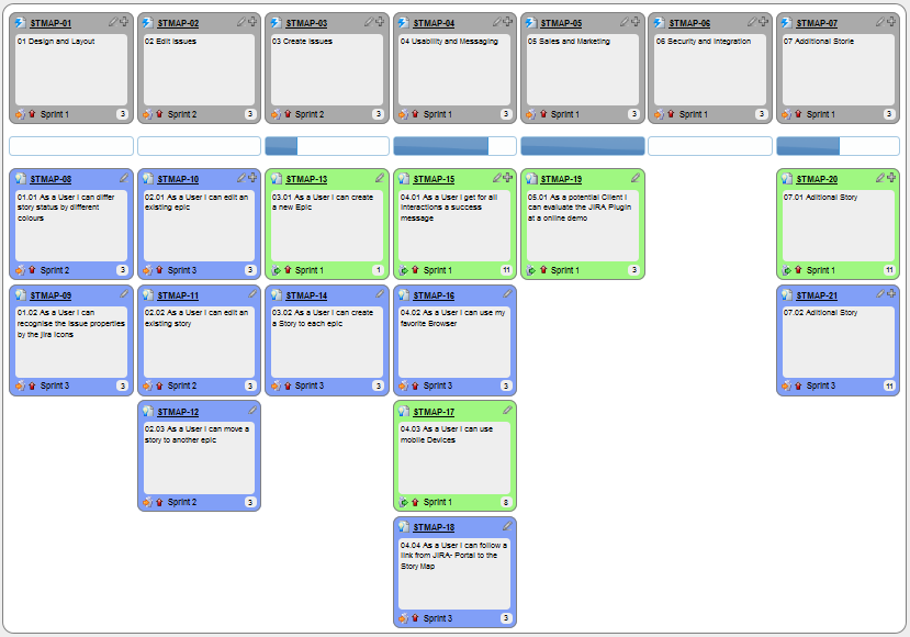
While use cases can be recorded on
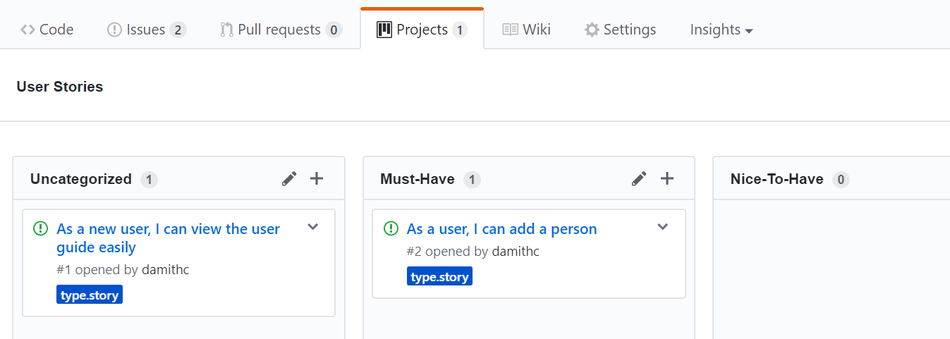
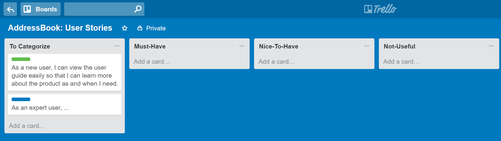
You can create issues for each of the user stories and use a GitHub Project Board to sort them into categories.
📦 Example Project Board:
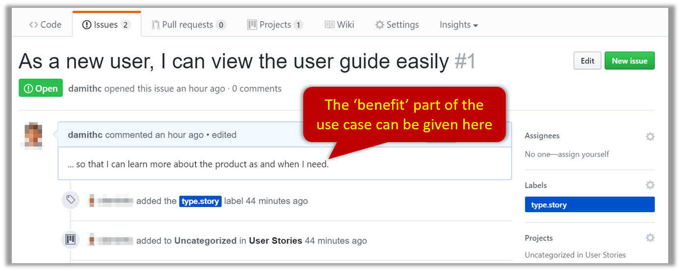
📦 Example Issue to represent a user story:
A video on GitHub Project Boards:
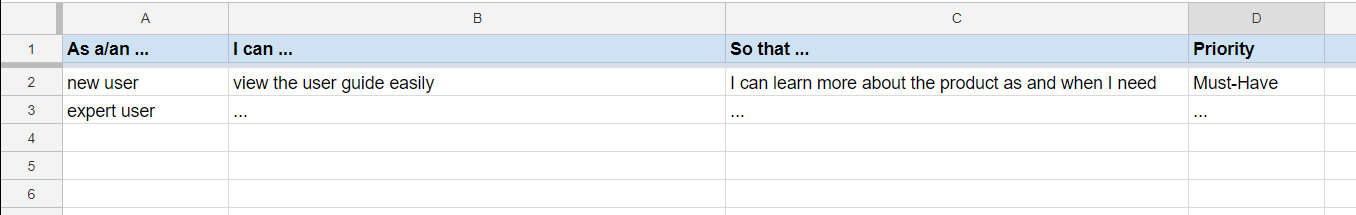
📦 Example Google Sheet for recording user stories:
📦 Example Trello Board for recording user stories:
Extreme programming (XP) is a software development methodology which is intended to improve software quality and responsiveness to changing customer requirements. As a type of agile software development, it advocates frequent "releases" in short development cycles, which is intended to improve productivity and introduce checkpoints at which new customer requirements can be adopted. [wikipedia, 2017.05.01]
This page in their website explains the difference between user stories and traditional requirements.
One of the biggest misunderstandings with user stories is how they differ from traditional requirements specifications. The biggest difference is in the level of detail. User stories should only provide enough detail to make a reasonably low risk estimate of how long the story will take to implement. When the time comes to implement the story developers will go to the customer and receive a detailed description of the requirements face to face.
Use Cases
Introduction
Use Case: A description of a set of sequences of actions, including variants, that a system performs to yield an observable result of value to an
Actor: An actor (in a use case) is a role played by a user. An actor can be a human or another system. Actors are not part of the system; they reside outside the system.
A use case describes an interaction between the user and the system for a specific functionality of the system.
- System:
ATM - Actor: Customer
- Use Case: Check account balance
- User inserts an ATM card
- ATM prompts for PIN
- User enters PIN
- ATM prompts for withdrawal amount
- User enters the amount
- ATM ejects the ATM card and issues cash
- User collects the card and the cash.
- System: A Learning Management System (LMS)
- Actor: Student
- Use Case: Upload file
- Student requests to upload file
- LMS requests for the file location
- Student specifies the file location
- LMS uploads the file
Unified Modeling Language (UML) is a graphical notation to describe various aspects of a software system. UML is the brainchild of three software modeling specialists James Rumbaugh, Grady Booch and Ivar Jacobson (also known as the Three Amigos). Each of them has developed their own notation for modeling software systems before joining force to create a unified modeling language (hence, the term ‘Unified’ in UML). UML is currently the de facto modeling notation used in the software industry.
Use cases capture the functional requirements of a system.
Identifying
A use case is an interaction between a system and its actors.
Actors in Use Cases
Actor: An actor (in a use case) is a role played by a user. An actor can be a human or another system. Actors are not part of the system; they reside outside the system.
📦 Some example actors for a Learning Management System
- Actors: Guest, Student, Staff, Admin,
ExamSys ,LibSys .
A use case can involve multiple actors.
- Software System: LearnSys
- Use case: UC01 conduct survey
- Actors: Staff, Student
An actor can be involved in many use cases.
- Software System: LearnSys
- Actor: Staff
- Use cases: UC01 conduct survey, UC02 Set Up Course Schedule, UC03 Email Class, ...
A single person/system can play many roles.
- Software System: LearnSys
- Person: a student
- Actors (or Roles): Student, Guest, Tutor
Many persons/systems can play a single role.
- Software System: LearnSys
- Actor(or role) : Student
- Persons that can play this role : undergraduate student, graduate student, a staff member doing a part-time course, exchange student
Use cases can be specified at various levels of detail.
📦 Consider the three use cases given below. Clearly, (a) is at a higher level than (b) and (b) is at a higher level than (c).
- System: LearnSys
- Use cases:
a. Conduct a survey
b. Take the survey
c. Answer survey question
While modeling user-system interactions,
💡 Start with high level use cases and progressively work toward lower level use cases.
💡 Be mindful at which level of details you are working on and not to mix use cases of different levels.Details
Writing use case steps
The main body of the use case is the sequence of steps that describes the interaction between the system and the actors. Each step is given as a simple statement describing who does what.
📦 An example of the main body of a use case.
- Student requests to upload file
- LMS requests for the file location
- Student specifies the file location
- LMS uploads the file
A use case describes only the externally visible behavior, not internal details, of a system i.e. should not mention give details that are not part of the interaction between the user and the system.
📦 This example use case step refers to behaviors not externally visible .
- LMS saves the file into the cache and indicates success.
A step gives the intention of the actor (not the mechanics). That means UI details are usually omitted. The idea is to leave as much flexibility to the UI designer as possible. That is, the use case specification should be as general as possible (less specific) about the UI.
❌ User right-clicks the text box and chooses ‘clear’ : this contains UI-specific details and is not a good use case step)
✅ User clears the input : this is better because it omits UI-specific details
This is how you can include repetitive steps in a scenario.
Software System: Square game Use case:
- A Player starts the game.
- SquareGame asks for player names.
- Each Player enters his own name.
- SquareGame shows the order of play.
- SquareGame prompts for the current Player to throw die.
- Current Player adjusts the throw speed.
- Current Player triggers the die throw.
- Square Game shows the face value of the die.
- Square Game moves the Player's piece accordingly.
Steps 5-9 are repeated for each Player, and for as many rounds as required until a Player reaches the 100th square. - Square Game shows the Winner.
Use case ends.
The Main Success Scenario (MSS) describes the most straightforward interaction for a given use case, which assumes that nothing goes wrong. This is also called the Basic Course of Action or the Main Flow of Events of a use case.
- System: Online Banking System (OBS)
- Use case: UC23 - Transfer Money
- Actor: User
- MSS:
- User chooses to transfer money.
- OBS requests for details of the transfer.
- User enters the requested details.
- OBS requests for confirmation.
- OBS transfers the money and displays the new account balance.
- Use case ends.
Note how the MSS assumes that all entered details are correct and ignores problems such as timeouts, network outages etc. Fro example, MSS does not tell us what happens if the user enters an incorrect data.
Extensions are "add-on"s to the MSS that describe exceptional/alternative flow of events. They describe variations of the scenario that can happen if certain things are not as expected by the MSS. Extensions appear below the MSS.
📦 This example adds some extensions to the use case in the previous example.
- System: Online Banking System (OBS)
- Use case: UC23 - Transfer Money
- Actor: User
- MSS:
- User chooses to transfer money.
- OBS requests for details of the transfer.
- User enters the requested details.
- OBS requests for confirmation.
- OBS transfers the money and displays the new account balance.
- Use case ends.
- Extensions:
- 3a. OBS detects an error in the entered data.
- 3a1. OBS requests for the correct data.
- 3a2. User enters new data.
- Steps 3a1-3a2 are repeated until the data entered are correct.
- Use case resumes from step 4.
- 3b. User requests to effect the transfer in a future date.
- 3b1. OBS requests for confirmation.
- 3b2. User confirms future transfer.
- Use case ends.
- *a. At any time, User chooses to cancel the transfer.
- *a1. OBS requests to confirm the cancellation.
- *a2. User confirms the cancellation.
- Use case ends.
- *b. At any time, 120 seconds lapse without any input from the User.
- *b1. OBS cancels the transfer.
- *b2. OBS informs the User of the cancellation.
- Use case ends.
- 3a. OBS detects an error in the entered data.
Note that the numbering style is not a universal rule but a widely used convention. Based on that convention,
- either of the extensions marked
3a.and3b.can happen just after step3of the MSS. - the extension marked as
*a.can happen at any step (hence, the*).
When separating extensions from the MSS, keep in mind that the MSS should be self-contained. That is, the MSS should give us a complete usage scenario.
Also note that it is not useful to mention events such as power failures or system crashes as extensions because the system cannot function beyond such catastrophic failures.
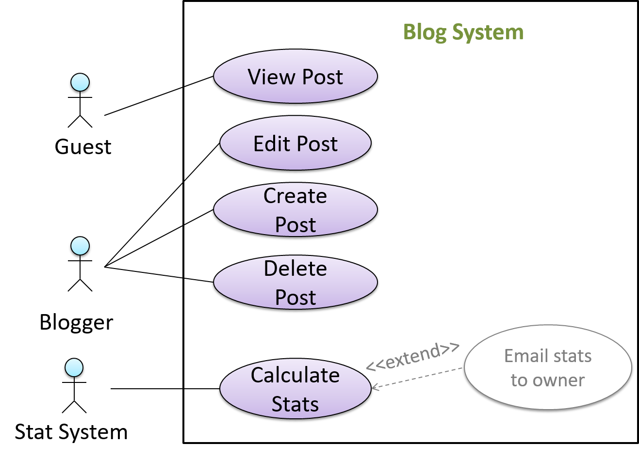
In use case diagrams you can use the << extend >> arrows to show extensions. Note the direction of the arrow is from the extension to the use case it extends and the arrow uses a dashed line.
A use case can include another use case. Underlined text is commonly used to show an inclusion of a use case.
📦 This use case includes two other use cases, one in step 1 and one in step 2.
- Software System: LearnSys
- Use case: UC01 - Conduct Survey
- Actors: Staff, Student
- MSS:
- Staff creates the survey (UC44).
- Student completes the survey (UC50).
- Staff views the survey results.
- Use case ends.
Inclusions are useful,
- when you don't want to clutter a use case with too many low-level steps.
- when a set of steps is repeated in multiple use cases.
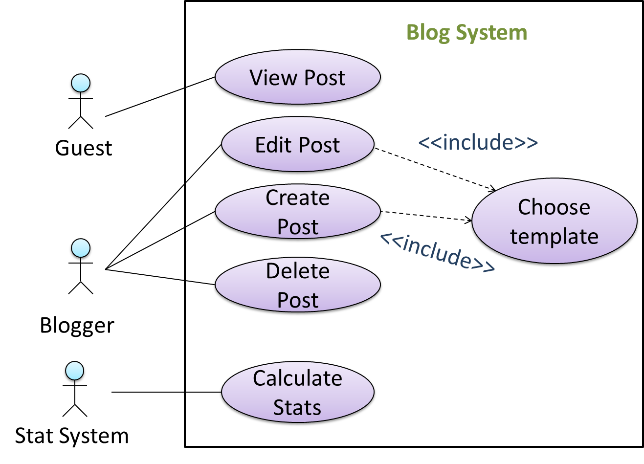
We use a dotted arrow and a << include >> annotation to show use case inclusions in a use case diagram. Note how the arrow direction is different from the << extend >> arrows.
Preconditions specify the specific state we expect the system to be in before the use case starts.
- Software System: Online Banking System
- Use case: UC23 - Transfer Money
- Actor: User
- Preconditions: User is logged in.
- MSS:
- User chooses to transfer money.
- OBS requests for details for the transfer.
- ...
Guarantees specify what the use case promises to give us at the end of its operation.
- Software System: Online Banking System
- Use case: UC23 - Transfer Money
- Actor: User
- Preconditions: User is logged in.
- Guarantees:
- Money will be deducted from the source account only if the transfer to the destination account is successful
- The transfer will not result in the account balance going below the minimum balance required.
- MSS:
- User chooses to transfer money.
- OBS requests for details for the transfer.
- ...
Usage
You can use actor generalization in use case diagrams using a symbol similar to that of UML notation for inheritance.
📦 In this example, actor Blogger can do all the use cases the actor Guest can do, as a result of the actor generalization relationship given in the diagram.
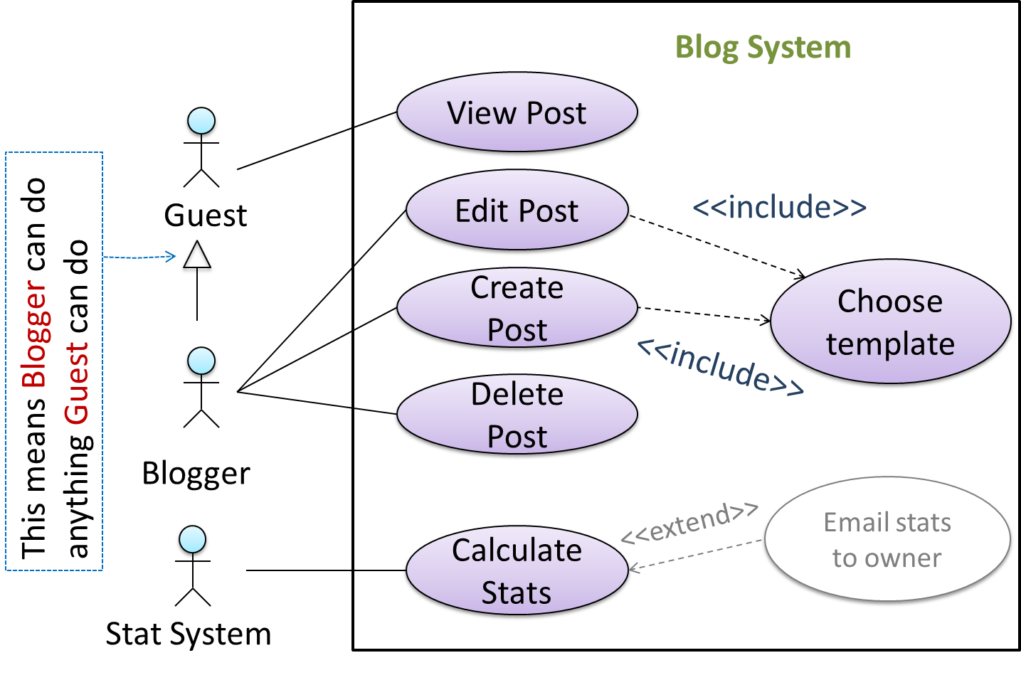
💡 Do not over-complicate use case diagrams by trying to include everything possible. A use case diagram is a brief summary of the use cases that is used as a starting point. Details of the use cases can be given in the use case descriptions.
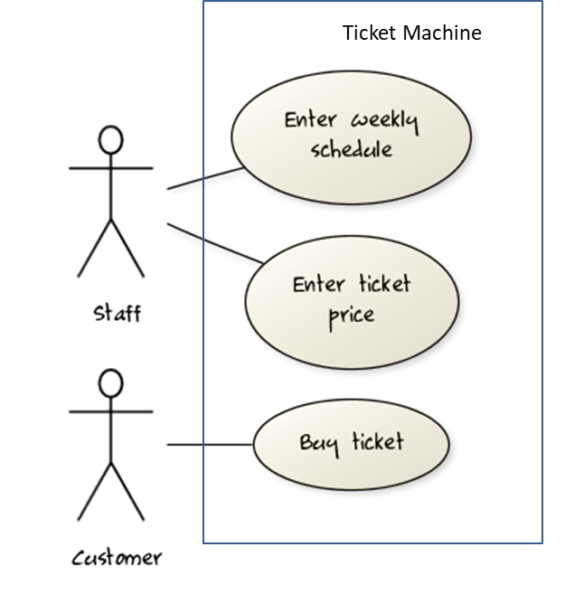
Some include ‘System’ as an actor to indicate that something is done by the system itself without being initiated by a user or an external system.
📦 The diagram below can be used to indicate that the system generates daily reports at midnight.
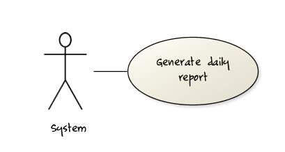
However, others argue that only use cases providing value to an external user/system should be shown in the use case diagram. For example, they argue that ‘view daily report’ should be the use case and generate daily report is not
to be shown in the use case diagram because it is simply something the system has to do to support the view daily report use case.
We recommend that you follow the latter view (i.e. not to use System as a user). Limit use cases for modeling behaviors that involve an external actor.
UML is not very specific about the text contents of a use case. Hence, there are many styles for writing use cases. For example, the steps can be written as a continuous paragraph. Use cases should be easy to read. Note that there is no strict rule about writing all details of all steps or a need to use all the elements of a use case.
There are some advantages of documenting system requirements as use cases:
- Because they use a simple notation and plain English descriptions, they are easy for users to understand and give feedback.
- They decouple user intention from mechanism (note that use cases should not include UI-specific details), allowing the system designers more freedom to optimize how a functionality is provided to a user.
- Identifying all possible extensions encourages us to consider all situations that a software product might face during its operation.
- Separating typical scenarios from special cases encourages us to optimize the typical scenarios.
One of the main disadvantages of use cases is that they are not good for capturing requirements that does not involve a user interacting with the system. Hence, they should not be used as the sole means to specify requirements.
Glossary
What
Glossary: A glossary serves to ensure that all stakeholders have a common understanding of the noteworthy terms, abbreviation, acronyms etc.
📦 Here is a partial glossary from a variant of the Snakes and Ladders game:
- Conditional square: A square that specifies a specific face value which a player has to throw before his/her piece can leave the square.
- Normal square: a normal square does not have any conditions, snakes, or ladders in it.
Supplementary Requirements
What
A supplementary requirements section can be used to capture requirements that do not fit elsewhere. Typically, this is where most
Requirements → Requirements →
Non-Functional Requirements
There are two kinds of requirements:
- Functional requirements specify what the system should do.
- Non-functional requirements specify the constraints under which system is developed and operated.
📦 Some examples of non-functional requirement categories:
- Data requirements e.g. size,
volatility ,persistency etc., - Environment requirements e.g. technical environment in which system would operate or need to be compatible with.
- Accessibility, Capacity, Compliance with regulations, Documentation, Disaster recovery, Efficiency, Extensibility, Fault tolerance, Interoperability, Maintainability, Privacy, Portability, Quality, Reliability, Response time, Robustness, Scalability, Security, Stability, Testability, and more ...
- Business/domain rules: e.g. the size of the minefield cannot be smaller than five.
- Constraints: e.g. the system should be backward compatible with data produced by earlier versions of the system; system testers are available only during the last month of the project; the total project cost should not exceed $1.5 million.
- Technical requirements: e.g. the system should work on both 32-bit and 64-bit environments.
- Performance requirements: e.g. the system should respond within two seconds.
- Quality requirements: e.g. the system should be usable by a novice who has never carried out an online purchase.
- Process requirements: e.g. the project is expected to adhere to a schedule that delivers a feature set every one month.
- Notes about project scope: e.g. the product is not required to handle the printing of reports.
- Any other noteworthy points: e.g. the game should not use images deemed offensive to those injured in real mine clearing activities.
We should spend extra effort in digging NFRs out as early as possible because NFRs are easier to miss e.g., stakeholders tend to think of functional requirements first and sometimes they are critical to the success of the software. E.g. A web application that is too slow or that has low security is unlikely to succeed even if it has all the right functionality.
Given below are some requirements of TEAMMATES (an online peer evaluation system for education). Which one of these are non-functional requirements?
- a. The response to any use action should become visible within 5 seconds.
- b. The application admin should be able to view a log of user activities.
- c. The source code should be open source.
- d. A course should be able to have up to 2000 students.
- e. As a student user, I can view details of my team members so that I can know who they are.
- f. The user interface should be intuitive enough for users who are not IT-savvy.
- g. The product is offered as a free online service.
(a)(c)(d)(f)(g)
Explanation: (b) are (e) are functions available for a specific user types. Therefore, they are functional requirements. (a), (c), (d), (f) and (g) are either constraints on functionality or constraints on how the project is done, both of which are considered non-functional requirements.
SECTION: DESIGN
Design
Introduction
What
Design in the creative process of transforming the problem into a solution; the solution is also called design. -- 📖 Software Engineering Theory and Practice, Shari Lawrence; Atlee, Joanne M. Pfleeger
Software design has two main aspects:
- Product/external design: designing the external behavior of the product to meet the users' requirements. This is usually done by product designers with the input from business analysts, user experience experts, user representatives, etc.
- Implementation/internal design: designing how the product will be implemented to meet the required external behavior. This is usually done by software architects and software engineers.
Design Fundamentals
Abstraction
What
Abstraction is a technique for dealing with complexity. It works by establishing a level of complexity (or an aspect) we are interested in, and suppressing the more complex details below that level (or irrelevant to that aspect).
Most programs are written to solve complex problems involving large amounts of intricate details. It is impossible to deal with all these details at the same time. The guiding principle of abstraction stipulates that we capture only details that are relevant to the current perspective or the task at hand.
Ignoring lower level data items and thinking in terms of bigger entities is called data abstraction.
📦 Within a certain software component, we might deal with a user data type, while ignoring the details contained in the user data item such as name, and date of birth. These details have been ‘abstracted away’ as they do not affect the task of that software component.
Control abstraction abstracts away details of the actual control flow to focus on tasks at a simplified level.
📦 print(“Hello”) is an abstraction of the actual output mechanism within the computer.
Abstraction can be applied repeatedly to obtain progressively higher levels of abstractions.
📦 An example of different levels of data abstraction: a File is a data item that is at a higher level than an array and an array is at a higher level than a bit.
📦 An example of different levels of control abstraction: execute(Game) is at a higher level than print(Char) which is at a higher than an Assembly language instruction MOV.
Coupling
What
Coupling is a measure of the degree of dependence between components, classes, methods, etc. Low coupling indicates that a component is less dependent on other components. High coupling (aka tight coupling or strong coupling) is discouraged due to the following disadvantages:
- Maintenance is harder because a change in one module could cause changes in other modules coupled to it (i.e. a ripple effect).
- Integration is harder because multiple components coupled with each other have to be integrated at the same time.
- Testing and reuse of the module is harder due to its dependence on other modules.
📦 In the example below, design A appears to have a more coupling between the components than design B.
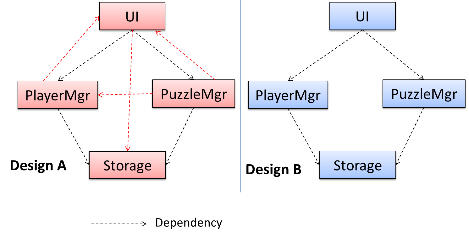
How
X is coupled to Y if a change to Y can potentially require a change in X.
📦 If Foo class calls the method Bar#read(), Foo is coupled to Bar because a change to Bar can potentially (but not always) require a change in the Foo class
e.g. if the signature of the Bar#read() is changed, Foo needs to change as well, but a change to the Bar#write() method may not require a change in the Foo class because Foo does not call Bar#write().
class Foo{
    ...
    new Bar().read();
    ...
}

class Bar{
    void read(){
        ...
    }

    void write(){
        ...
    }
}
📦 Some examples of coupling: A is coupled to B if,
Ahas access to the internal structure ofB(this results in a very high level of coupling)AandBdepend on the same global variableAcallsBAreceives an object ofBas a parameter or a return valueAinherits fromBAandBare required to follow the same data format or communication protocol
Types of Coupling
Some examples of different coupling types:
- Content coupling: one module modifies or relies on the internal workings of another module e.g., accessing local data of another module
- Common/Global coupling: two modules share the same global data
- Control coupling: one module controlling the flow of another, by passing it information on what to do e.g., passing a flag
- Data coupling: one module sharing data with another module e.g. via passing parameters
- External coupling: two modules share an externally imposed convention e.g., data formats, communication protocols, device interfaces.
- Subclass coupling: a class inherits from another class. Note that a child class is coupled to the parent class but not the other way around.
- Temporal coupling: two actions are bundled together just because they happen to occur at the same time e.g. extracting a contiguous block of code as a method although the code block contains statements unrelated to each other
Cohesion
What
Cohesion is a measure of how strongly-related and focused the various responsibilities of a component are. A highly-cohesive component keeps related functionalities together while keeping out all other unrelated things.
Higher cohesion is better. Disadvantages of low cohesion (aka weak cohesion):
- Impedes the understandability of modules as it is difficult to express module functionalities at a higher level.
- Lowers maintainability because a module can be modified due to unrelated causes (reason: the module contains code unrelated to each other) or many many modules may need to be modified to achieve a small change in behavior (reason: because the code realated to that change is not localized to a single module).
- Lowers reusability of modules because they do not represent logical units of functionality.
How
Cohesion can be present in many forms. Some examples:
- Code related to a single concept is kept together, e.g. the Student component handles everything related to students.
- Code that is invoked close together in time is kept together, e.g. all code related to initializing the system is kept together.
- Code that manipulates the same data structure is kept together, e.g. the
GameArchivecomponent handles everything related to the storage and retrieval of game sessions.
📦 Suppose a Payroll application contains a class that deals with writing data to the database. If the class include some code to show an error dialog to the user if the database is unreachable, that class is not cohesive because it seems to be interacting with the user as well as the database.
Modeling
Introduction
What
A model is a representation of something else.
📦 A
A class diagram is a diagram drawn using the UML modelling notation.
📦 An example class diagram:
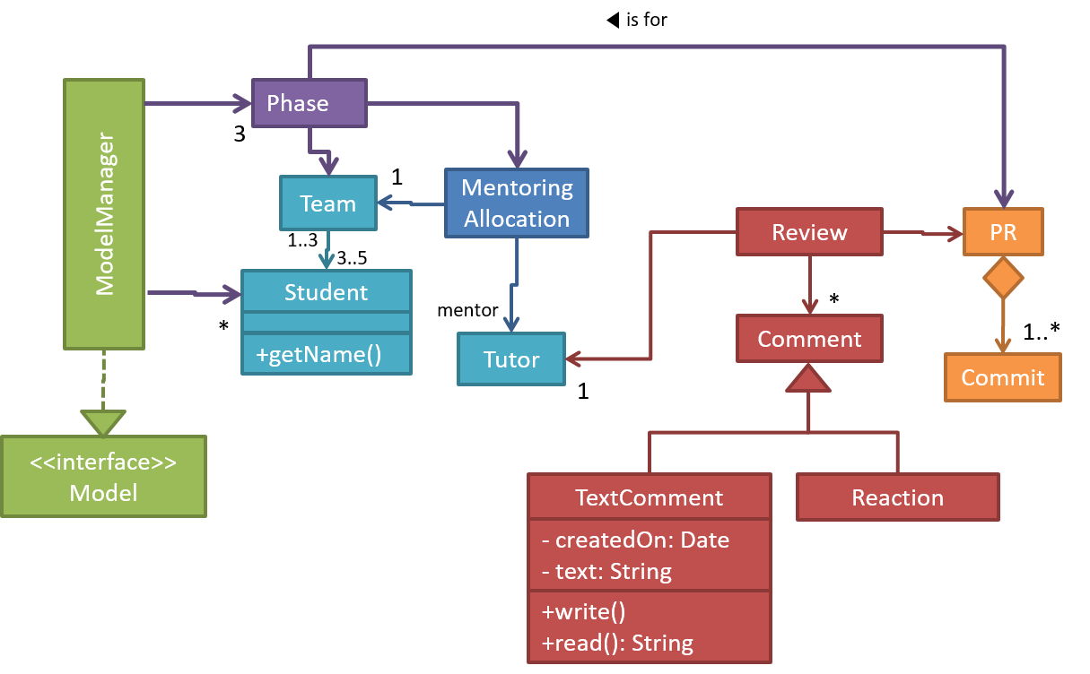
A model provides a simpler view of a complex entity because a model captures only a selected aspect. This omission of some aspects implies models are
Design → Design Fundamentals → Abstraction →
What
Abstraction is a technique for dealing with complexity. It works by establishing a level of complexity (or an aspect) we are interested in, and suppressing the more complex details below that level (or irrelevant to that aspect).
Most programs are written to solve complex problems involving large amounts of intricate details. It is impossible to deal with all these details at the same time. The guiding principle of abstraction stipulates that we capture only details that are relevant to the current perspective or the task at hand.
Ignoring lower level data items and thinking in terms of bigger entities is called data abstraction.
📦 Within a certain software component, we might deal with a user data type, while ignoring the details contained in the user data item such as name, and date of birth. These details have been ‘abstracted away’ as they do not affect the task of that software component.
Control abstraction abstracts away details of the actual control flow to focus on tasks at a simplified level.
📦 print(“Hello”) is an abstraction of the actual output mechanism within the computer.
Abstraction can be applied repeatedly to obtain progressively higher levels of abstractions.
📦 An example of different levels of data abstraction: a File is a data item that is at a higher level than an array and an array is at a higher level than a bit.
📦 An example of different levels of control abstraction: execute(Game) is at a higher level than print(Char) which is at a higher than an Assembly language instruction MOV.
📦 A class diagram captures the structure of the software design but not the behavior.
Multiple models of the same entity may be needed to capture it fully.
📦 In addition to a class diagram (or even multiple class diagrams), a number of other diagrams may be needed to capture various interesting aspects of the software.
How
In software development, models are useful in several ways:
a) To analyze a complex entity related to software development.
📦 Some examples of using models for analysis:
- Models of the problem domain (i.e. the environment in which the software is expected to solve a problem) can be built to aid the understanding of the problem to be solved.
- When planning a software solution, models can be created to figure out how the solution is to be built. An architecture diagram is such a model.
b) To communicate information among stakeholders. Models can be used as a visual aid in discussions and documentations.
📦 Some examples of using models to communicate:
- An architect can use an architecture diagram to explain the high-level design of the software to developers.
- A business analyst can use a use case diagram to explain to the customer the functionality of the system.
- A class diagram can be reverse-engineered from code so as to help explain the design of a component to a new developer.
c) As a blueprint for creating software. Models can be used as instructions for building software.
📦 Some examples of using models to as blueprints:
- A senior developer draws a class diagram to propose a design for an OOP software and passes it to a junior programmer to implement.
- A software tool allows users to draw UML models using its interface and the tool automatically generates the code based on the model.
Model-driven development (MDD), also called Model-driven engineering, is an approach to software development that strives to exploits models as blueprints. MDD uses models as primary engineering artifacts when developing software. That is, the system is first created in the form of models. After that, the models are converted to code using code-generation techniques (usually, automated or semi-automated, but can even involve manual translation from model to code). MDD requires the use of a very expressive modeling notation (graphical or otherwise), often specific to a given problem domain. It also requires sophisticated tools to generate code from models and maintain the link between models and the code. One advantage of MDD is that the same model can be used to create software for different platforms and different languages. MDD has a lot of promise, but it is still an emerging technology
Further reading:
- Martin Fowler's view on MDD - TLDR: he is sceptical
- 5 types of Model Driven Software Development - A more optimistic view, although an old article
UML Models 
The following diagram uses the class diagram notation to show the different types of UML diagrams.

source:https://en.wikipedia.org/
Modeling Structures
Class Diagrams (Basics)
Associations among objects/classes play an important role in an OO solution.
The most basic class diagram is a bunch of classes with some solid lines among them to represent associations, such as this one.
📦 An example class diagram showing associations between classes.
In addition, associations can show additional decorations such as association labels, association roles, multiplicity and navigability to add more information to a class diagram.
📦 Here is the same class diagram shown earlier but with some additional information included:
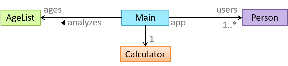
Object Diagrams
An object diagram shows an object structure at a given point of time.
Object Oriented Domain Models
The analysis process for identifying objects and object classes is recognized as one of the most difficult areas of object-oriented development. --Ian Sommerville, in the book Software Engineering
Class diagrams can also be used to model objects in the
📦 OO domain model of a snakes and ladders game is given below.
Description: Snakes and ladders game is played by two or more players using a board and a die. The board has 100 squares marked 1 to 100. Each player owns one piece. Players take turns to throw the die and advance their piece by the number of squares they earned from the die throw. The board has a number of snakes. If a player’s piece lands on a square with a snake head, the piece is automatically moved to the square containing the snake’s tail. Similarly, a piece can automatically move from a ladder foot to the ladder top. The player whose piece is the first to reach the 100th square wins.
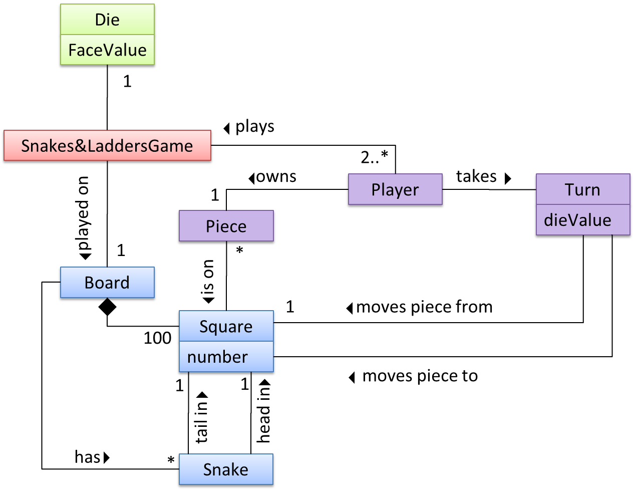
The above OO domain model omits the ladder class for simplicity. It can be included in a similar fashion to the Snake class.
OODMs do not contain solution-specific classes (i.e. classes that are used in the solution domain but do not exist in the problem domain). For example, a class called DatabaseConnection could appear in a class diagram but not usually in an OO domain model because DatabaseConnection is something related to a software solution but not an entity in the problem domain.
OODMs represents the class structure of the problem domain and not their behavior, just like class diagrams. To show behavior, use other diagrams such as sequence diagrams.
OODM notation is similar to class diagram notation but typically omit methods and navigability.
Deployment Diagrams
A deployment diagram shows a system's physical layout, revealing which pieces of software run on which pieces of hardware.
📦 An example deployment diagram:
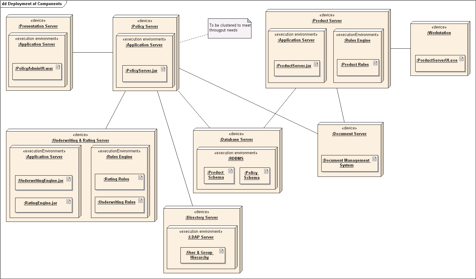
Component Diagrams
A component diagram is used to show how a system is divided into components and how they are connected to each other through interfaces.
📦 An example component diagram:
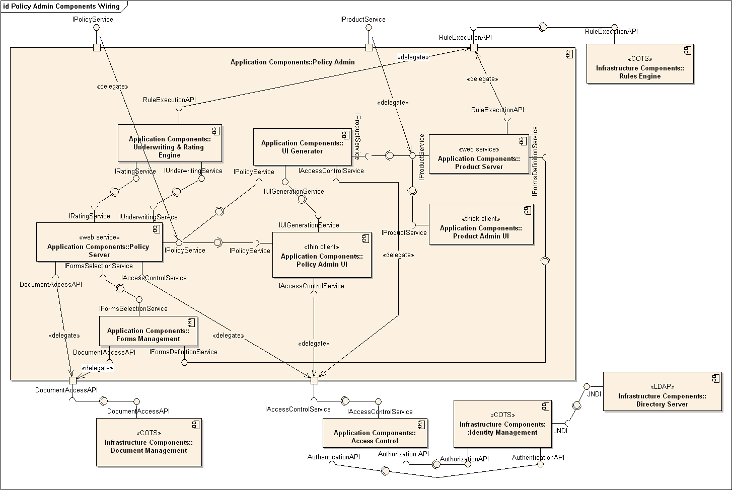
Package Diagrams
A package diagram shows packages and their dependencies. A package is a grouping construct for grouping UML elements (classes, use cases, etc.).
📦 Here is an example package diagram:
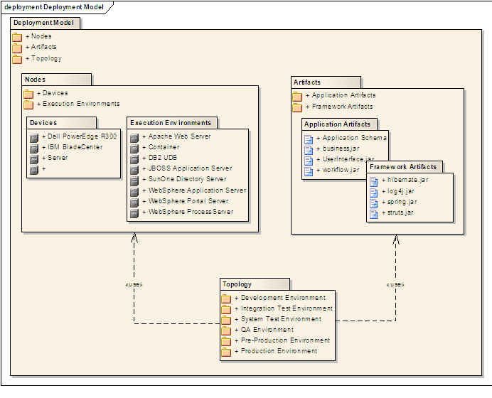
Composite Structure Diagrams
A composite structure diagram hierarchically decomposes a class into its internal structure.
📦 Here is an example composite structure diagram:
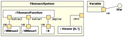
Modeling Behaviors
Activity Diagrams
Software projects often involve workflows. Workflows define the
Some examples in which a certain workflow is relevant to software project:
📦 A software that automates the work of an insurance company needs to take into account the workflow of processing an insurance claim.
📦 The algorithm of a price of code represents the workflow (i.e. the execution flow) of the code.
Understanding such workflows is important for the success of the software project.
Unified Modeling Language (UML) is a graphical notation to describe various aspects of a software system. UML is the brainchild of three software modeling specialists James Rumbaugh, Grady Booch and Ivar Jacobson (also known as the Three Amigos). Each of them has developed their own notation for modeling software systems before joining force to create a unified modeling language (hence, the term ‘Unified’ in UML). UML is currently the de facto modeling notation used in the software industry.
📦 An example activity diagram [source:wikipeida]:

The most basic activity diagram is simply a linear sequence of actions.
Some workflows have alternate paths where only one of the alternate paths is taken based on some condition.
In some workflows, multiple paths happen in parallel.
Sequence Diagrams - Basic
Sequence diagrams model interactions between entities for a given scenario.
📦 Consider the code below.
class Machine {

    Unit producePrototype() {
        Unit prototype = new Unit();
        for (int i = 0; i < 5; i++) {
            prototype.stressTest();
        }
        return prototype;
    }
}

class Unit {

    public void stressTest() {

    }
}
Here is the sequence diagram to model the interactions for the method call prouducePrototype() on a Machine object.
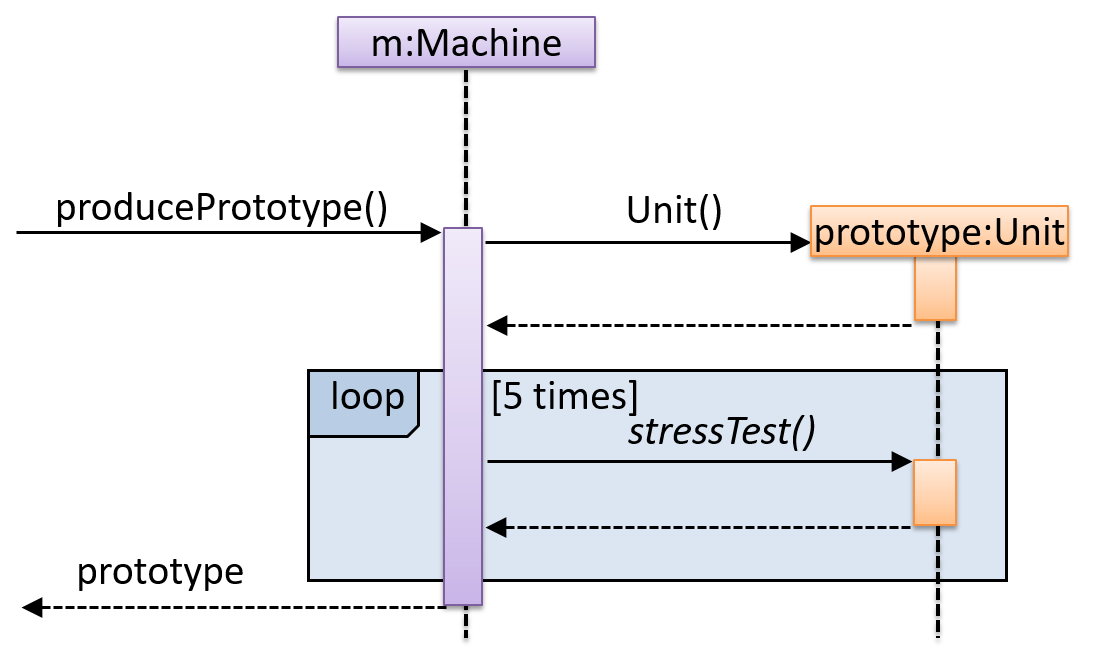
Use Case Diagrams
Use case diagrams model the mapping between features of a system and its user roles.
📦 A simple use case diagram:
Timing Diagrams
A timing diagram focus on timing constraints.
📦 Here is an example timing diagram:
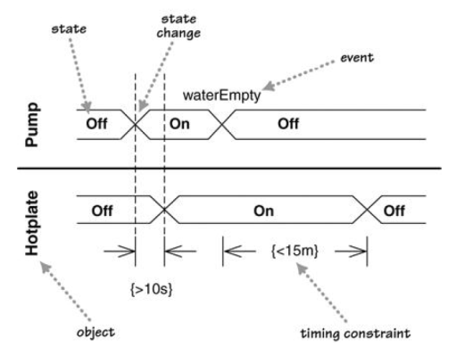
Adapted from: UML Distilled by Martin Fowler
Interaction Overview Diagrams
An Interaction overview diagrams is a combination of activity diagrams and sequence diagrams.
📦 An example:
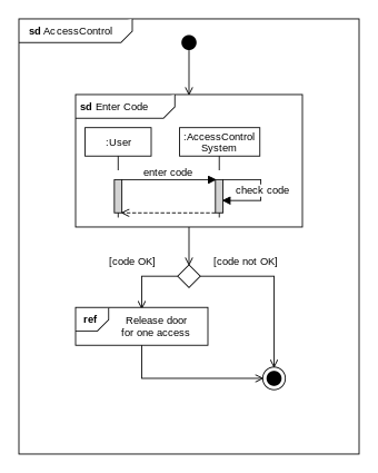
Communication Diagrams
A Communication diagrams are like sequence diagrams but emphasize the data links between the various participants in the interaction rather than the sequence of interactions.
📦 An example:
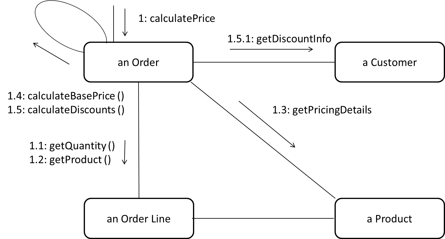
Adapted from: UML Distilled by Martin Fowler
State Machine Diagrams
A State Machine Diagram models state-dependent behavior.
📦 Consider how a CD player responds when the “eject CD” button is pushed:
- If the CD tray is already open, it does nothing.
- If the CD tray is already in the process of opening (opened half-way), it continues to open the CD tray.
- If the CD tray is closed and the CD is being played, it stops playing and opens the CD tray.
- If the CD tray is closed and CD is not being played, it simply opens the CD tray.
- If the CD tray is already in the process of closing (closed half-way), it waits until the CD tray is fully closed and opens it immediately afterwards.
What this means is that the CD player’s response to pushing the “eject CD” button depends on what it was doing at the time of the event. More generally, the CD player’s response to the event received depends on its internal state. Such a behavior is called a state-dependent behavior.
Often, state-dependent behavior displayed by an object in a system is simple enough that it needs no extra attention; such a behavior can be as simple as a conditional behavior like if x>y, then x=x-y. Occasionally,
objects may exhibit state-dependent behavior that is complex enough such that it needs to be captured into a separate model. Such state-dependent behavior can be modelled using UML state machine diagrams (SMD for short, sometimes
also called ‘state charts’, ‘state diagrams’ or ‘state machines’).
An SMD views the life-cycle of an object as consisting of a finite number of states where each state displays a unique behavior pattern. An SMD captures information such as the states an object can be in, during its lifetime, and how the object responds to various events while in each state and how the object transits from one state to another. In contrast to sequence diagrams that capture object behavior one scenario at a time, SMDs capture the object’s behavior over its full life cycle.
📦 An SMD for the Minesweeper game.
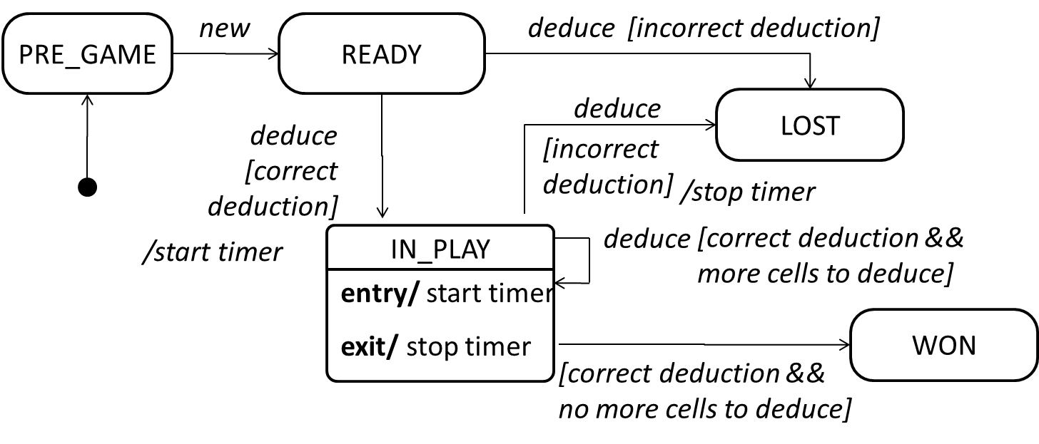
Modeling a Solution
Introduction
You can use models to analyze and design a software before you start coding.
Suppose You are planning to implement a simple minesweeper game that has a text based UI and a GUI. Given below is a possible OOP design for the game.

Before jumping into coding, you may want to find out things such as,
- Is this class structure is able to produce the behavior we want?
- What API should each class have?
- Do we need more classes?
To answer those questions, you can analyze the how the objects of these classes will interact with each other to produce the behavior you want.
Basic
As mentioned in [
Design → Modeling → Modeling a Solution →
Introduction
You can use models to analyze and design a software before you start coding.
Suppose You are planning to implement a simple minesweeper game that has a text based UI and a GUI. Given below is a possible OOP design for the game.
Before jumping into coding, you may want to find out things such as,
- Is this class structure is able to produce the behavior we want?
- What API should each class have?
- Do we need more classes?
To answer those questions, you can analyze the how the objects of these classes will interact with each other to produce the behavior you want.
Let us start by modelling a sample interaction between the person playing the game and the TextUi object.
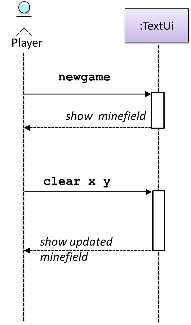
newgame and clear x y represent commands typed by the Player on the TextUi.
How does the TextUi object carry out the requests it has received from player? It would need to interact with other objects of the system. Because the Logic class is the one that controls the game logic, the TextUi needs to collaborate with Logic to fulfill the newgame request. Let us extend the model to capture that interaction.
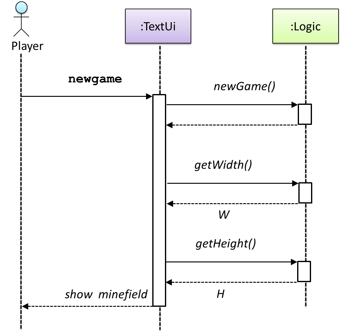
W = Width of the minefield; H = Height of the minefield
The above diagram assumes that W and H are the only information TextUi requires to display the minefield to the Player. Note that there could be other ways of doing this.
The Logic methods we conceptualized in our modelling so far are:
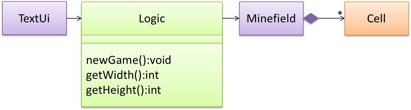
Now, let us look at what other objects and interactions are needed to support the newGame() operation. It is likely that a new Minefield object is created when the newGame() method is called.

Note that the behavior of the Minefield constructor has been abstracted away. It can be designed at a later stage.
Given below are the interactions between the player and the Text UI for the whole game.
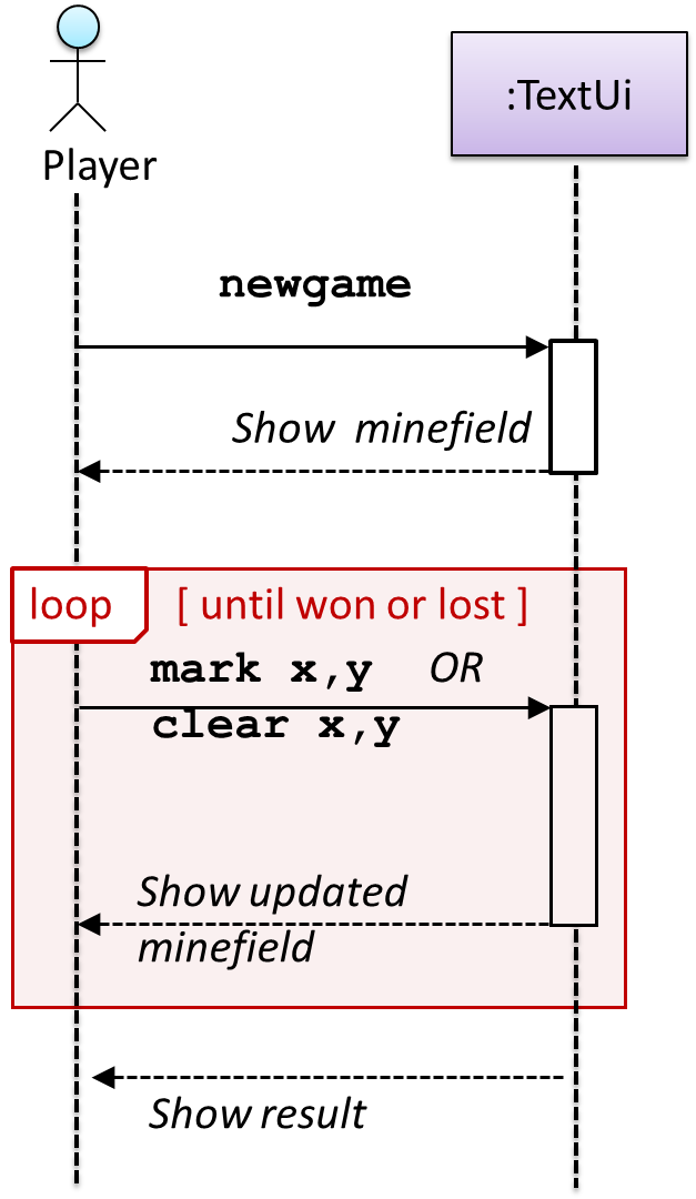
💡 Note that
📺 Defining the architecture-level APIs for a small Tic-Tac-Toe game:
Intermediate
Continuing with the example in [
Design → Modeling → Modeling a Solution →
Basic
As mentioned in [
Design → Modeling → Modeling a Solution →
Introduction
You can use models to analyze and design a software before you start coding.
Suppose You are planning to implement a simple minesweeper game that has a text based UI and a GUI. Given below is a possible OOP design for the game.
Before jumping into coding, you may want to find out things such as,
- Is this class structure is able to produce the behavior we want?
- What API should each class have?
- Do we need more classes?
To answer those questions, you can analyze the how the objects of these classes will interact with each other to produce the behavior you want.
Let us start by modelling a sample interaction between the person playing the game and the TextUi object.
newgame and clear x y represent commands typed by the Player on the TextUi.
How does the TextUi object carry out the requests it has received from player? It would need to interact with other objects of the system. Because the Logic class is the one that controls the game logic, the
TextUi needs to collaborate with Logic to fulfill the newgame request. Let us extend the model to capture that interaction.
W = Width of the minefield; H = Height of the minefield
The above diagram assumes that W and H are the only information TextUi requires to display the minefield to the Player. Note that there could be other ways of doing this.
The Logic methods we conceptualized in our modelling so far are:
Now, let us look at what other objects and interactions are needed to support the newGame() operation. It is likely that a new Minefield object is created when the newGame() method is called.
Note that the behavior of the Minefield constructor has been abstracted away. It can be designed at a later stage.
Given below are the interactions between the player and the Text UI for the whole game.
💡 Note that
📺 Defining the architecture-level APIs for a small Tic-Tac-Toe game:
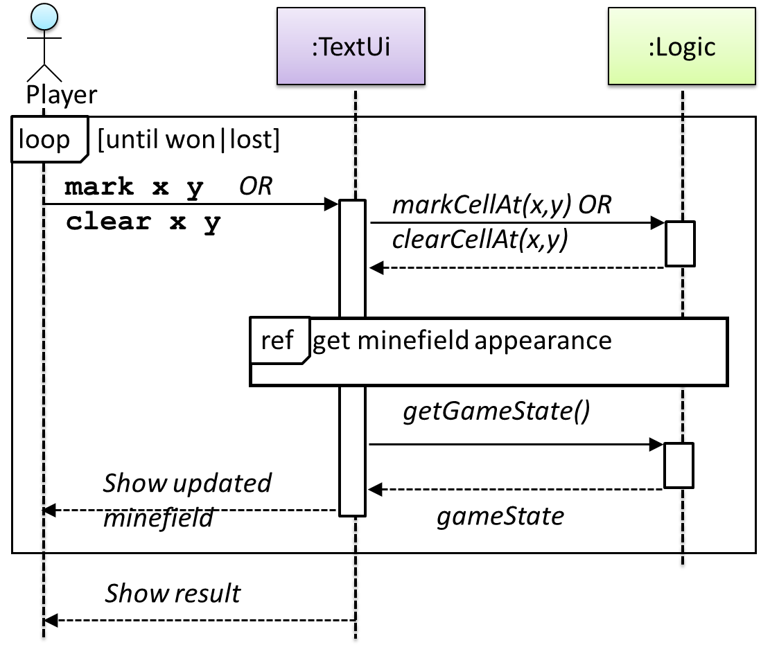
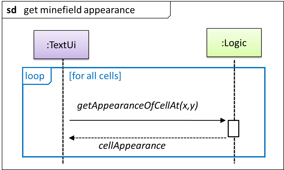
This interaction adds the following methods to the Logic class
clearCellAt(int x, int y)markCellAt(int x, int y)getGameState() :GAME_STATE (GAME_STATE: READY, IN_PLAY, WON, LOST, …)
And it adds the following operation to Logic API:
getAppearanceOfCellAt(int,int):CELL_APPEARANCE (CELL_APPEARANCE: HIDDEN, ZERO, ONE, TWO, THREE, …, MARKED, INCORRECTLY_MARKED, INCORRECTLY_CLEARED)
In the above design, TextUi does not access Cell objects directly. Instead, it gets values of type CELL_APPEARANCE from Logic to be displayed as a minefield to the player. Alternatively, each
cell or the entire Minefield can be passed directly to TextUi.
Here is the updated class diagram:
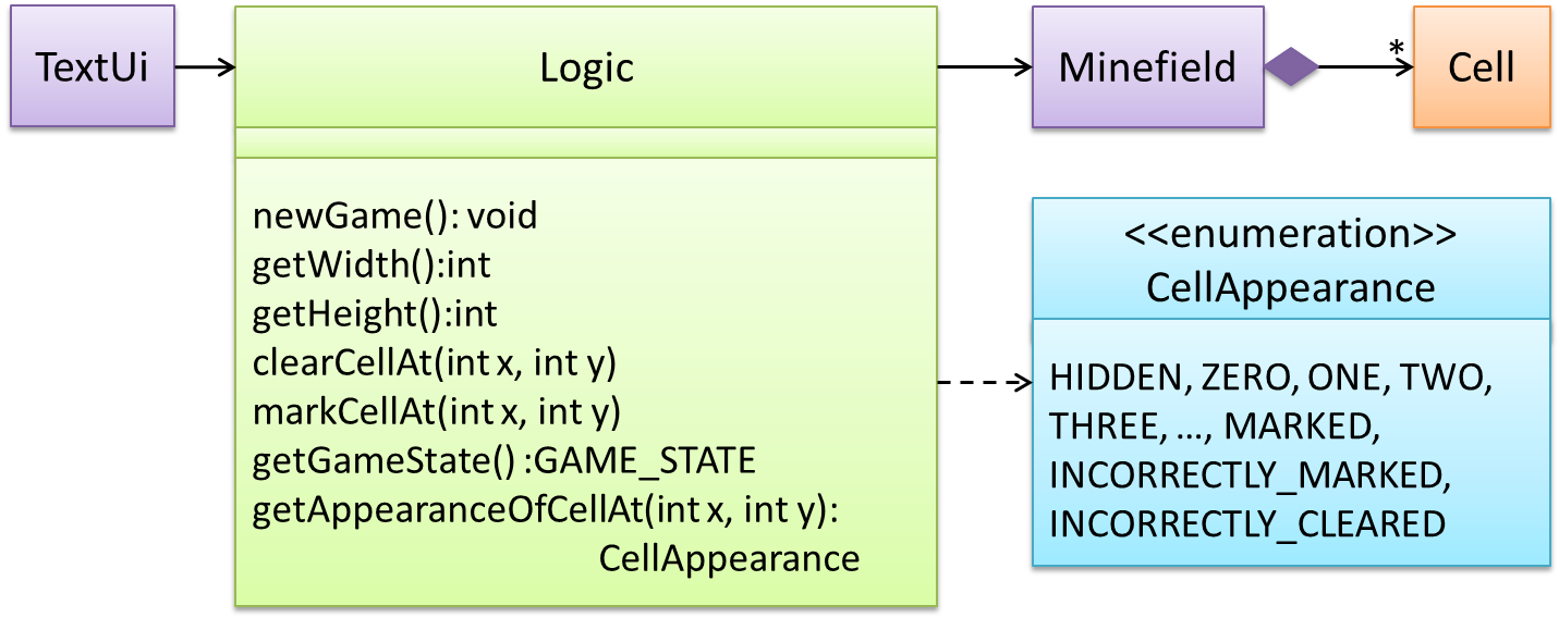
The above is for the case when Actor Player interacts with the system using a text UI. Additional operations (if any) required for the GUI can be discovered similarly. Suppose Logic supports a reset() operation.
We can model it like this:
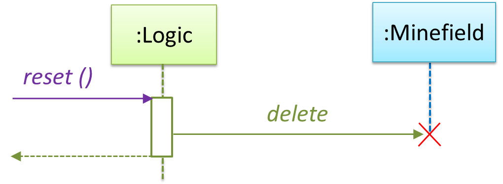
Our current model assumes that the Minefield object has enough information (i.e. H, W, and mine locations) to create itself.
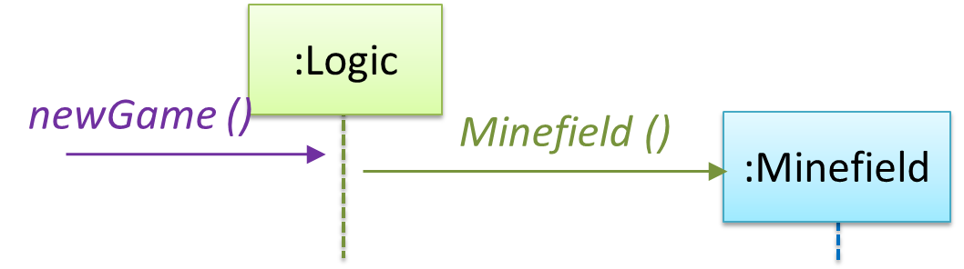
An alternative is to have a ConfigGenerator object that generates a string containing the minefield information as shown below.
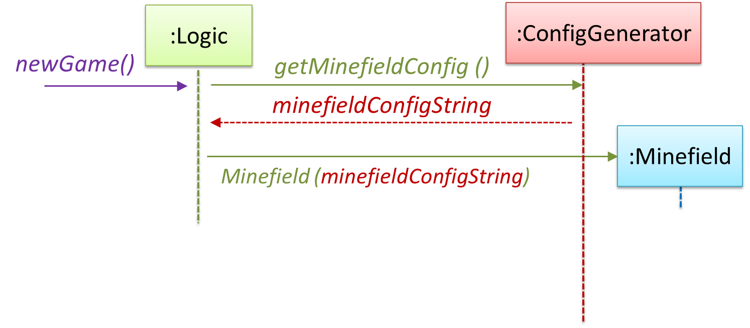
In addition, getWidth(), getHeight(), markCellAt(x,y) and clearCellAt(x,y) can be handled like this.
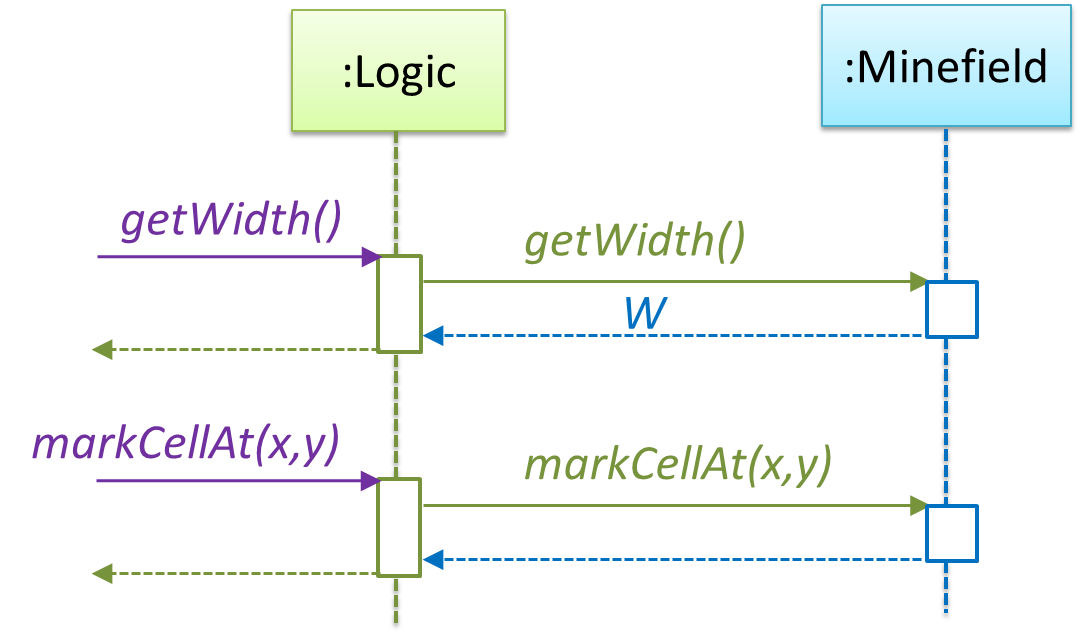
The updated class diagram:
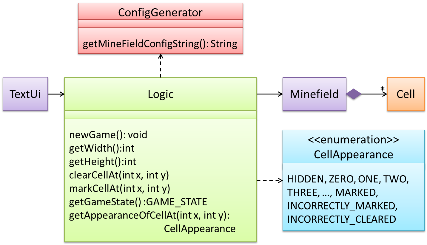
How is getGameState() operation supported? Given below are two ways (there could be other ways):
Minefieldclass knows the state of the game at any time.Logicclass retrieves it from theMinefieldclass as and when required.Logicclass maintains the state of the game at all times.
Here’s the SD for option 1.
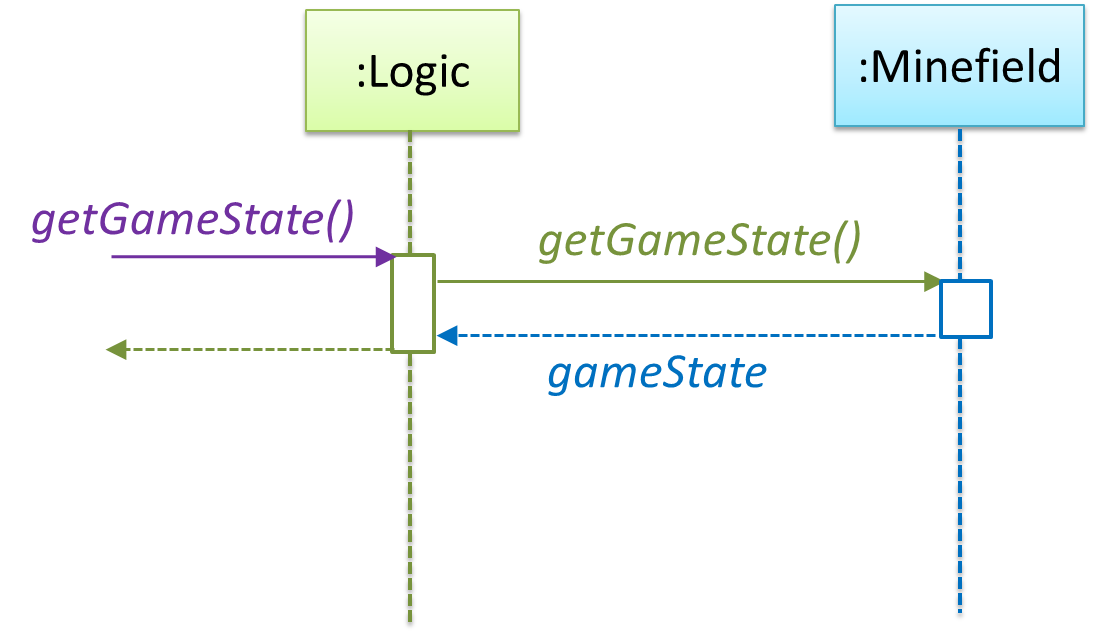
Here’s the SD for option 2. Here, assume that the game state is updated after every mark/clear action.
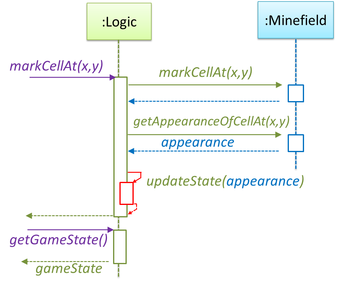
It is now time to explore what happens inside the Minefield constructor? One way is to design it as follows.
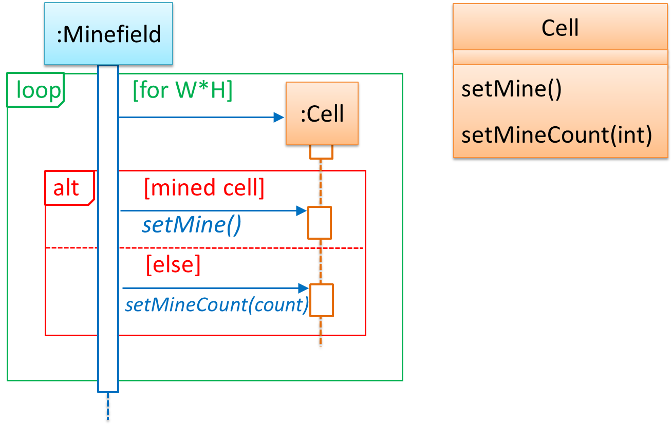
Now let us assume that Minesweeper supports a ‘timing’ feature.
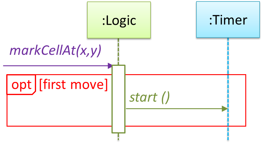
Updated class diagram:
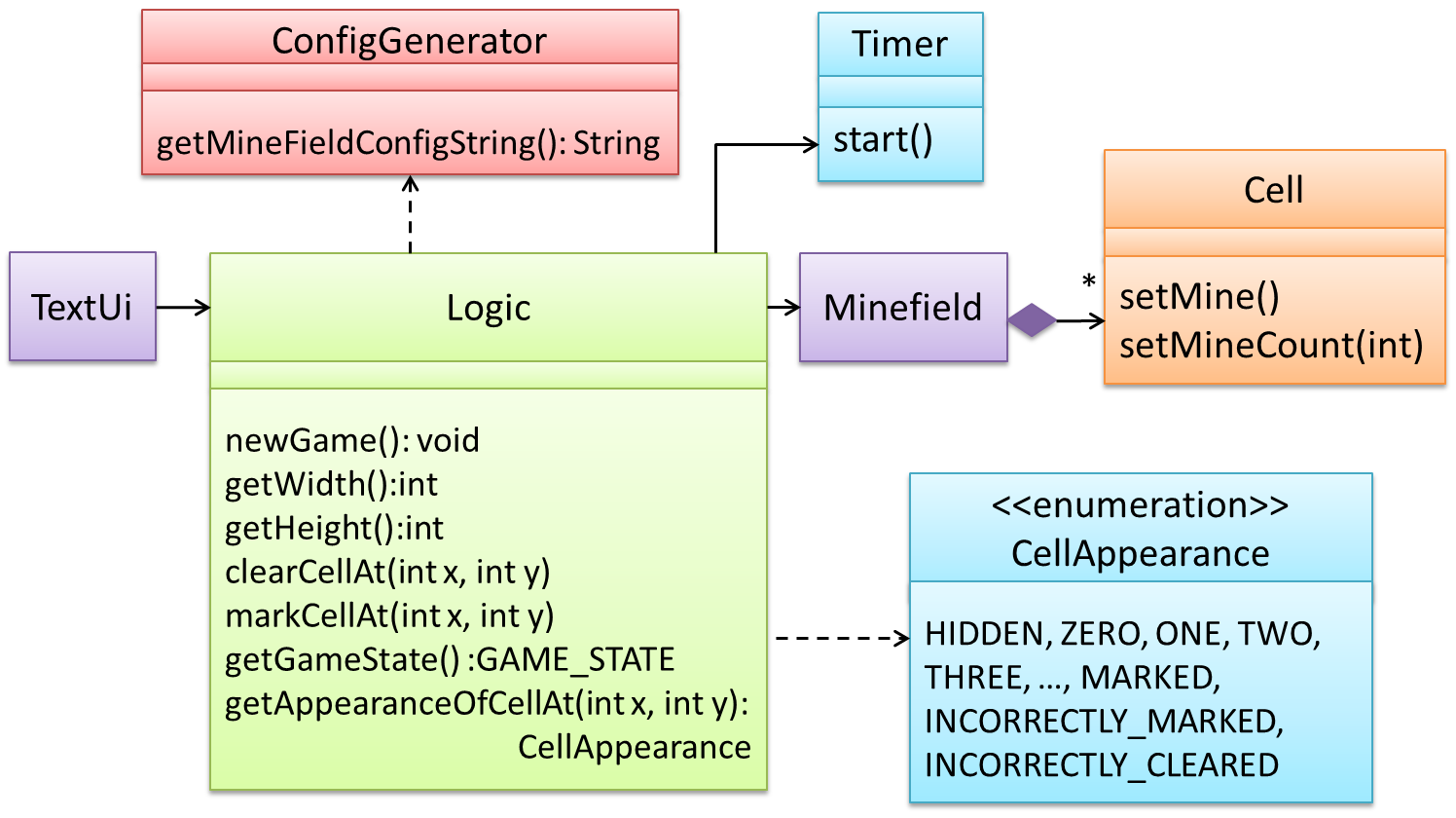
💡 When designing components, it is not necessary to draw elaborate UML diagrams capturing all details of the design. They can be done as rough sketches. For example, draw sequence diagrams only when you are not sure which operations are required by each class, or when you want to verify that your class structure can indeed support the required operations.
Software Architecture
Introduction
What
The software architecture of a program or computing system is the structure or structures of the system, which comprise software elements, the externally visible properties of those elements, and the relationships among them. Architecture is concerned with the public side of interfaces; private details of elements—details having to do solely with internal implementation—are not architectural. -- Software Architecture in Practice (2nd edition), Bass, Clements, and Kazman
The software architecture shows the overall organization of the system and can be viewed as a very high-level design. It usually consists of a set of interacting components that fit together to achieve the required functionality. It should be a simple and technically viable structure that is well-understood and agreed-upon by everyone in the development team, and it forms the basis for the implementation.
📦 A possible architecture for a Minesweeper game
 |
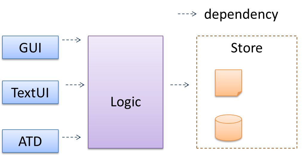 |
Main components:
GUI: Graphical user interfaceTextUi: Textual user interfaceATD: An automated test driver used for testing the game logicLogic: computation and logic of the gameStore: storage and retrieval of game data (high scores etc.)
The architecture is typically designed by the software architect, who provides the technical vision of the system and makes high-level (i.e. architecture-level) technical decisions about the project.
Architecture Diagrams
Reading
Architecture diagrams are free-form diagrams. There is no universally adopted standard notation for architecture diagrams. Any symbol that reasonably describes the architecture may be used.
📦 Some example architecture diagrams from elsewhere:


source: https://commons.wikimedia.org

source: https://commons.wikimedia.org

source: https://commons.wikimedia.org
Drawing
While architecture diagrams have no standard notation, try to follow these basic guidelines when drawing them.
-
Minimize the variety of symbols. If the symbols you choose do not have widely-understood meanings e.g. A drum symbol is widely-understood as representing a database, explain their meaning.
-
Avoid the indiscriminate use of double-headed arrows to show interactions between components.
📦Consider the two architecture diagrams of the same software given below. Because Diagram 2 uses double headed arrows, the important fact that GUI has a bi-directional dependency with the Logic component is no longer captured.
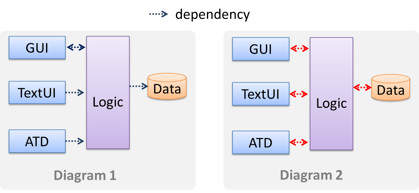
Architectural Styles
Introduction
What
Software architectures follow various high-level styles (aka architectural patterns), just like
📦 n-tier style, client-server style, event-driven style, transaction processing style, service-oriented style, pipes-and-filters style, message-driven style, broker style, ...
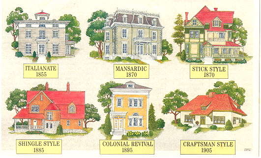
source: https://inspectapedia.com
N-tier Architectural Style
What
In the n-tier style, higher layers make use of services provided by lower layers. Lower layers are independent of higher layers. Other names: multi-layered, layered.
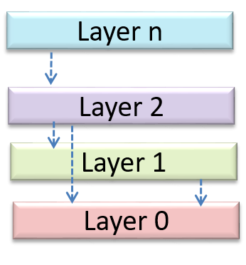
📦 Operating systems and network communication software often use n-tier style.
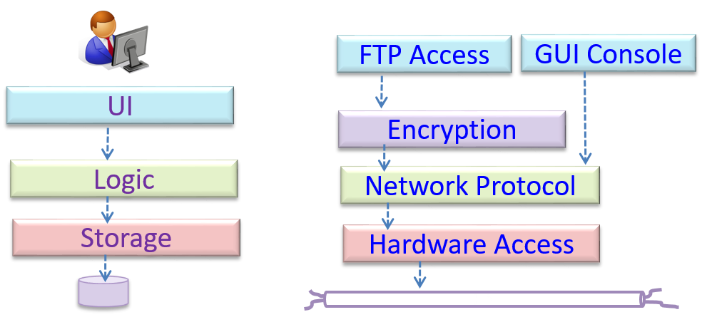
Client-Server Architectural Style
What
The client-server style has at least one component playing the role of a server and at least one client component accessing the services of the server. This is an architectural style used often in distributed applications.
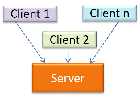
📦 The online game and teh Web application below uses the client-server style.
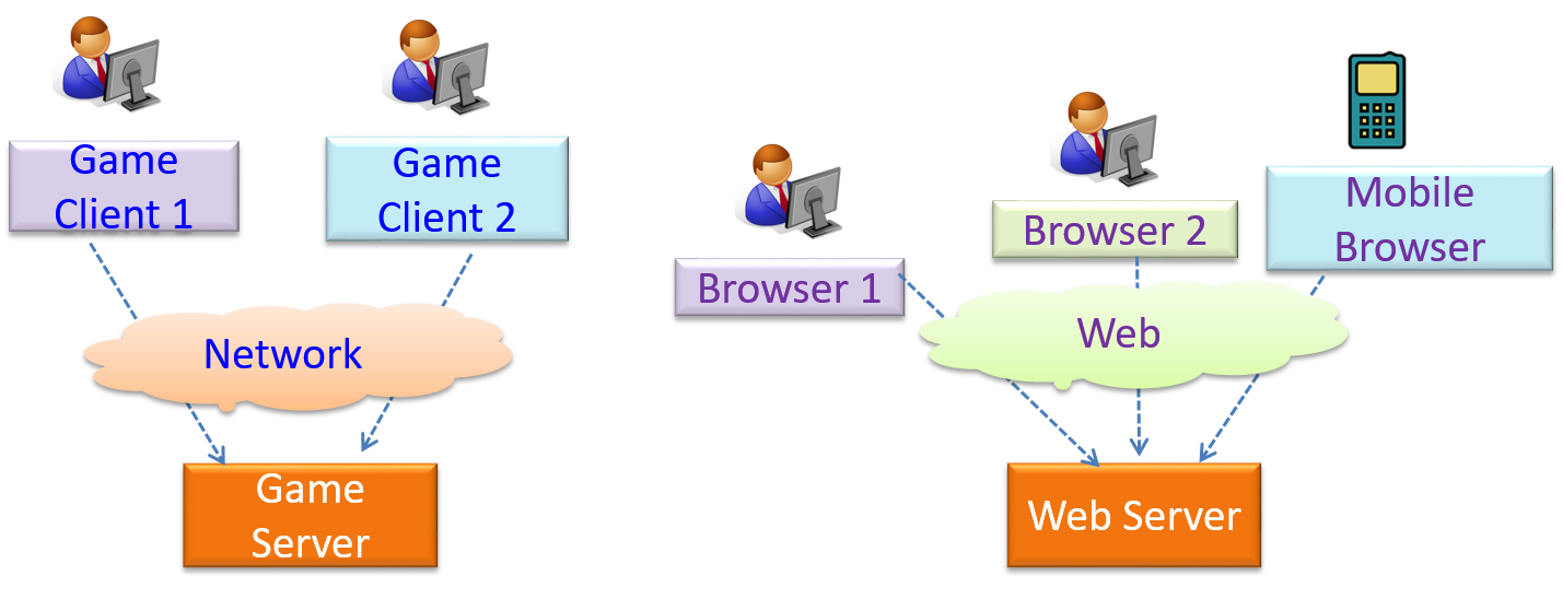
Transaction Processing Architectural Style
What
The transaction processing style divides the workload of the system down to a number of transactions which are then given to a dispatcher that controls the execution of each transaction. Task queuing, ordering, undo etc. are handled by the dispatcher.
📦 In this example from a Banking system, transactions are generated by the terminals used by
Service-oriented Architectural Style
What
The service-oriented architecture (SOA) style builds applications by combining functionalities packaged as programmatically accessible services. SOA aims to achieve interoperability between distributed services, which may not even be implemented using the same programming language. A common way to implement SOA is through the use of XML web services where the web is used as the medium for the services to interact, and XML is used as the language of communication between service providers and service users.
📦 Suppose that Amazon.com provides a web service for customers to browse and buy merchandise, while HSBC provides a web service for merchants to charge HSBC credit cards. Using these web services, an ‘eBookShop’ web application can be developed that allows HSBC customers to buy merchandise from Amazon and pay for them using HSBC credit cards. Because both Amazon and HSBC services follow the SOA architecture, their web services can be reused by the web application, even if all three systems use different programming platforms.
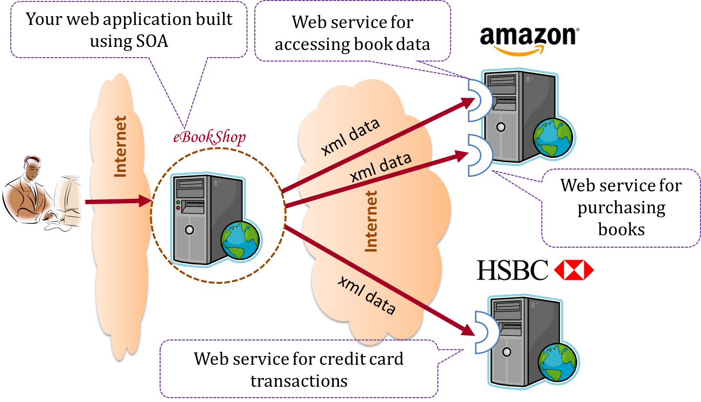
Event-driven Architectural Style
What
Event-driven style controls the flow of the application by detecting
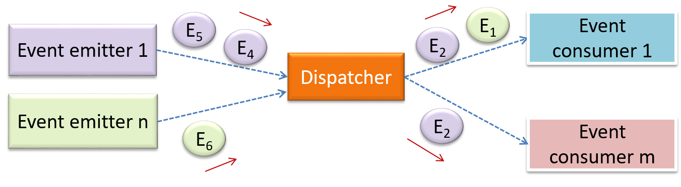
📦 When the ‘button clicked’ event occurs in a GUI, that event can be transmitted to components that are interested in reacting to that event. Similarly, events detected at a Printer port can be transmitted to components related to operating the Printer. The same event can be sent to multiple consumers too.
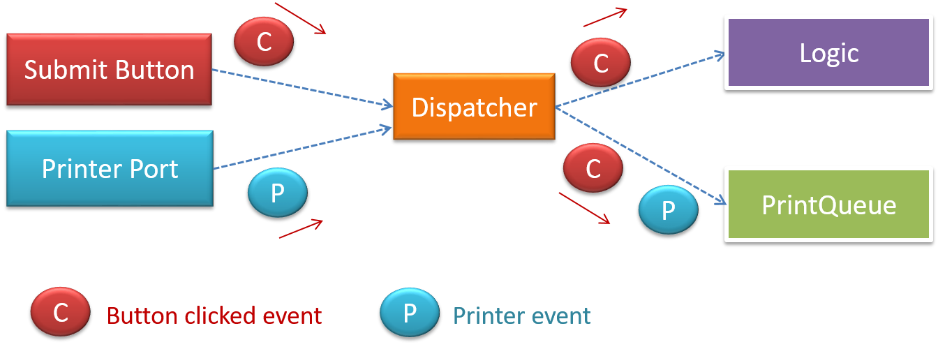
More
More Styles
Other well-known architectural styles include the pipes-and-filters architectures, the broker architectures, the peer-to-peer architectures, and the message-oriented architectures.
Using Styles
Most applications use a mix of these architectural styles.
📦 An application can use a client-server architecture where the server component comprises several layers, i.e. it uses the n-Tier architecture.
Software Design Patterns
Introduction
What
Design Pattern : An elegant reusable solution to a commonly recurring problem within a given context in software design.
In software development, there are certain problems that recur in a certain context.
📦 Some examples of recurring design problems:
| Design Context | Recurring Problem |
|---|---|
| Assembling a system that makes use of other existing systems implemented using different technologies | What is the best architecture? |
| UI needs to be updated when the data in application backend changes | How to initiate an update to the UI when data changes without coupling the backend to the UI? |
After repeated attempts at solving such problems, better solutions are discovered and refined over time. These solutions are known as design patterns, **a term popularized by the seminal book Design Patterns: Elements of Reusable Object-Oriented Software by the so-called "Gang of Four"** (GoF) book written by Eric Gamma, Richard Helm, Ralph Johnson,and John Vlissides
Format
The common format to describe a pattern consists of the following components:
- Context: The situation or scenario where the design problem is encountered.
- Problem: The main difficulty to be resolved.
- Solution: The core of the solution. It is important to note that the solution presented only includes the most general details, which may need further refinement for a specific context.
- Anti-patterns (optional): Commonly used solutions, which are usually incorrect and/or inferior to the Design Pattern.
- Consequences (optional): Identifying the pros and cons of applying the pattern.
- Other useful information (optional): Code examples, known uses, other related patterns, etc.
Singleton Pattern
What
Context
A certain classes should have no more than just one instance (e.g. the main controller class of the system). These single instances are commonly known as singletons.
Problem
A normal class can be instantiated multiple times by invoking the constructor.
Solution
Make the constructor of the singleton class private, because a public constructor will allow others to instantiate the class at will. Provide a public class-level method to
access the single instance.
Example:
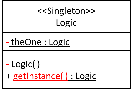
Implementation
Here is the typical implementation of how the Singleton pattern is applied to a class:
class Logic {
    private static Logic theOne = null;

    private Logic() {
        ...
    }

    public static Logic getInstance() {
        if (theOne == null) {
            theOne = new Logic();
        }
        return theOne;
    }
}
Notes:
- The constructor is
private, which prevents instantiation from outside the class. - The single instance of the singleton class is maintained by a
privateclass-level variable. - Access to this object is provided by a
publicclass-level operationgetInstance()which instantiates a single copy of the singleton class when it is executed for the first time. Subsequent calls to this operation return the single instance of the class.
If Logic was not a Singleton class, an object is created like this:
Logic m = new Logic();
But now, the Logic object needs to be accessed like this:
Logic m = Logic.getInstance();
Evaluation
Pros:
- easy to apply
- effective in achieving its goal with minimal extra work
- provides an easy way to access the singleton object from anywhere in the code base
Cons:
- The singleton object acts like a global variable that increases coupling across the code base.
- In testing, it is difficult to replace Singleton objects with stubs (static methods cannot be overridden)
- In testing, singleton objects carry data from one test to another even when we want each test to be independent of the others.
Given there are some significant cons, it is recommended that you apply the Singleton pattern when, in addition to requiring only one instance of a class, there is a risk of creating multiple objects by mistake, and creating such multiple objects has real negative consequences.
Abstraction Occurrence Pattern
What
Context
There is a group of similar entities that appears to be ‘occurrences’ (or ‘copies’) of the same thing, sharing lots of common information, but also differing in significant ways.
📦 In a library, there can be multiple copies of same book title. Each copy shares common information such as book title, author, ISBN etc. However, there are also significant differences like purchase date and barcode number (assumed to be unique for each copy of the book).
Other examples:
- Episodes of the same TV series
- Stock items of the same product model (e.g. TV sets of the same model).
Problem
Representing the objects mentioned previously as a single class would be problematic because it results in duplication of data which can lead to inconsistencies in data (if some of the duplicates are not updated consistently).
📦 Take for example the problem of representing books in a library. Assume that there could be multiple copies of the same title, bearing the same ISBN number, but different serial numbers.
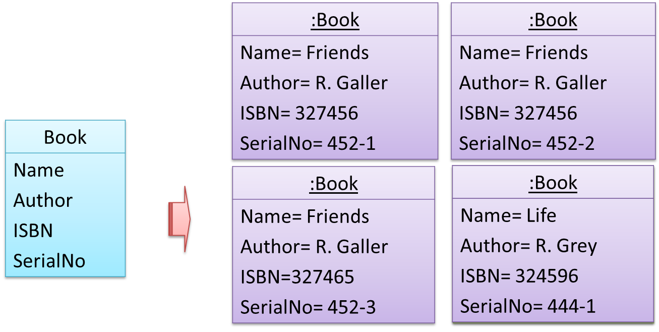
The above solution requires common information to be duplicated by all instances. This will not only waste storage space, but also creates a consistency problem. Suppose that after creating several copies of the same title, the librarian realized that the author name was wrongly spelt. To correct this mistake, the system needs to go through every copy of the same title to make the correction. Also, if a new copy of the title is added later on, the librarian (or the system) has to make sure that all information entered is the same as the existing copies to avoid inconsistency.
Anti-pattern
📦 Refer to the same Library example given above.
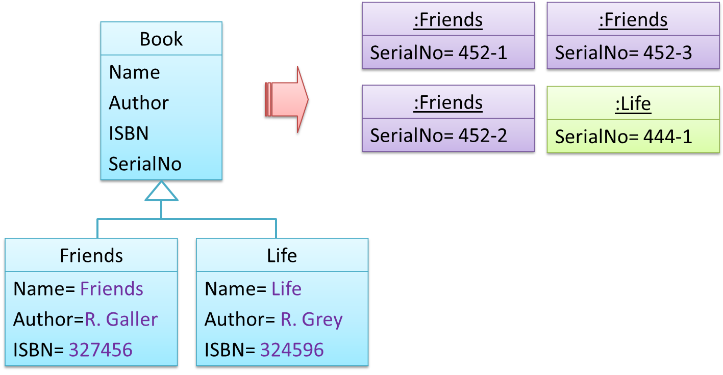
The design above segregates the common and unique information into a class hierarchy. Each book title is represented by a separate class with common data (i.e. Name, Author, ISBN) hard-coded in the class itself. This solution is problematic because each book title is represented as a class, resulting in thousands of classes (one for each title). Every time the library buys new books, the source code of the system will have to be updated with new classes.
Solution
Let a copy of an entity (e.g. a copy of a book)be represented by two objects instead of one, separating the common and unique information into two classes to avoid duplication.
📦 Given below is how the pattern is applied to the Library example:
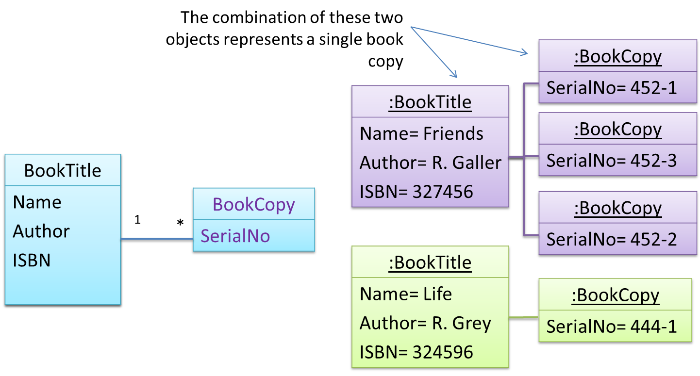
📦 Here's a more generic example:
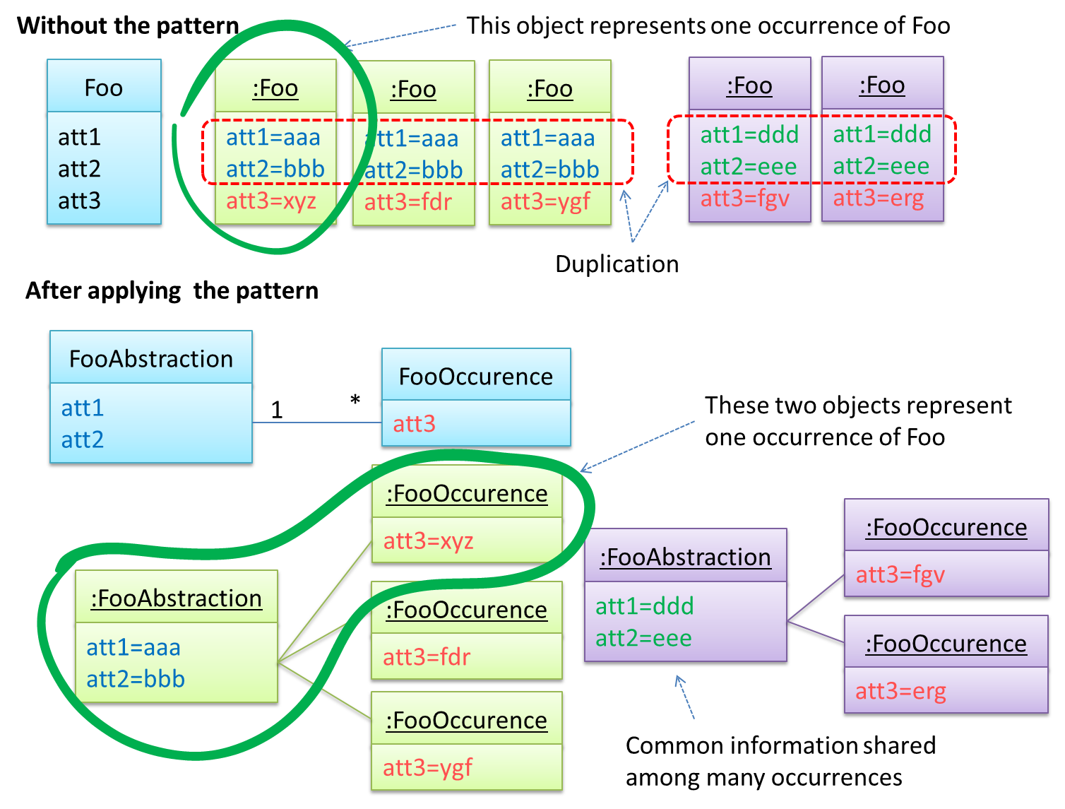
The general solution:
The << Abstraction >> class should hold all common information, and the unique information should be kept by the << Occurrence >> class. Note that ‘Abstraction’ and ‘Occurrence’ are not class
names, but roles played by each class. Think of this diagram as a meta-model (i.e. a ‘model of a model’) of the BookTitle-BookCopy class diagram given above.
Facade Pattern
What
Context
Components need to access functionality deep inside other components.
📦 The UI component of a Library system might want to access functionality of the Book class contained inside the Logic component.
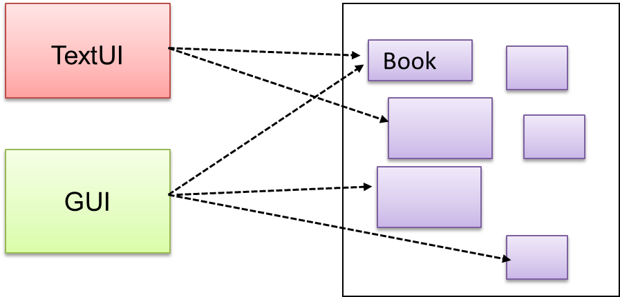
Problem
Access to the component should be allowed without exposing its internal details. e.g. the UI component should access the functionality of the Logic component without knowing that it contained a Book class within it.
Solution
Include a
📦 The following class diagram applies the Façade pattern to the Library System example. The LibraryLogic class is the Facade class.
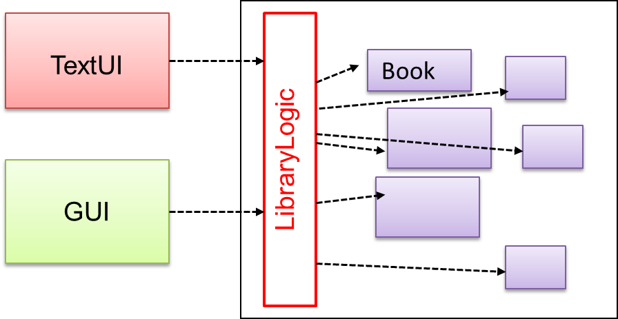
Command Pattern
What
Context
A system is required to execute a number of commands, each doing a different task. For example, a system might have to support Sort, List, Reset commands.
Problem
It is preferable that some part of the code executes these commands without having to know each command type. e.g., there can be a CommandQueue object that is responsible for queuing commands and executing them without knowledge of what each command does.
Solution
The essential element of this pattern is to have a general << Command >> object that can be passed around, stored, executed, etc without knowing the type of command (i.e. via polymorphism).
Let us examine an example application of the pattern first:
📦 In the example solution below, the CommandCreator creates List, Sort, and Reset Command objects and adds them to the CommandQueue object. The CommandQueue object
treats them all as Command objects and performs the execute/undo operation on each of them without knowledge of the specific Command type. When executed, each Command object will access the DataStore object to carry out its task. The Command class can also be an abstract class or an interface.
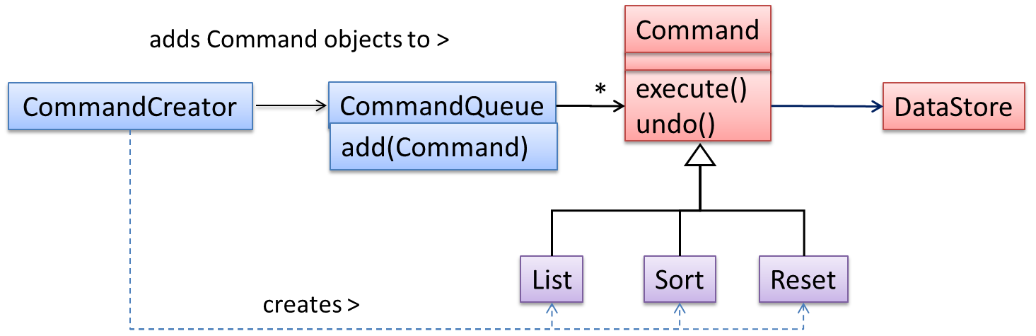
The general form of the solution is as follows.
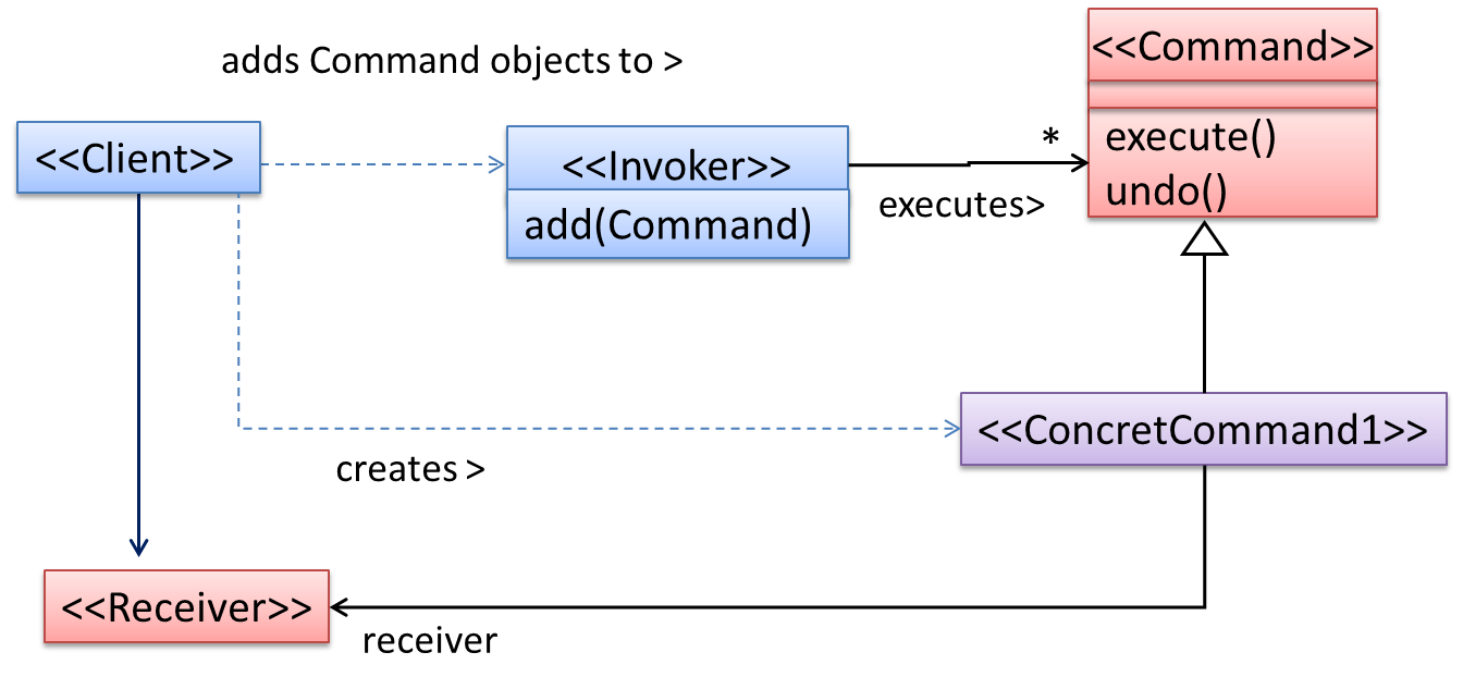
The << Client >> creates a << ConcreteCommand >> object, and passes it to the << Invoker >>. The << Invoker >> object treats all commands as
a general << Command >> type. << Invoker >> issues a request by calling execute() on the command. If a command is undoable, << ConcreteCommand >> will
store the state for undoing the command prior to invoking execute(). In addition, the << ConcreteCommand >> object may have to be linked to any << Receiver >> of the command (
<< Invoker >>. Note that an application of the command pattern does not have to follow the structure given above.
Model View Controller (MVC) Pattern
What
Context
Most applications support storage/retrieval of information, displaying of information to the user (often via multiple UIs having different formats), and changing stored information based on external inputs.
Problem
To reduce coupling resulting from the interlinked nature of the features described above.
Solution
To decouple data, presentation, and control logic of an application by separating them into three different components: Model, View and Controller.
- View: Displays data, interacts with the user, and pulls data from the model if necessary.
- Controller: Detects UI events such as mouse clicks, button pushes and takes follow up action. Updates/changes the model/view when necessary.
- Model: Stores and maintains data. Updates views if necessary.
The relationship between the components can be observed in the diagram below. Typically, the UI is the combination of view and controller.
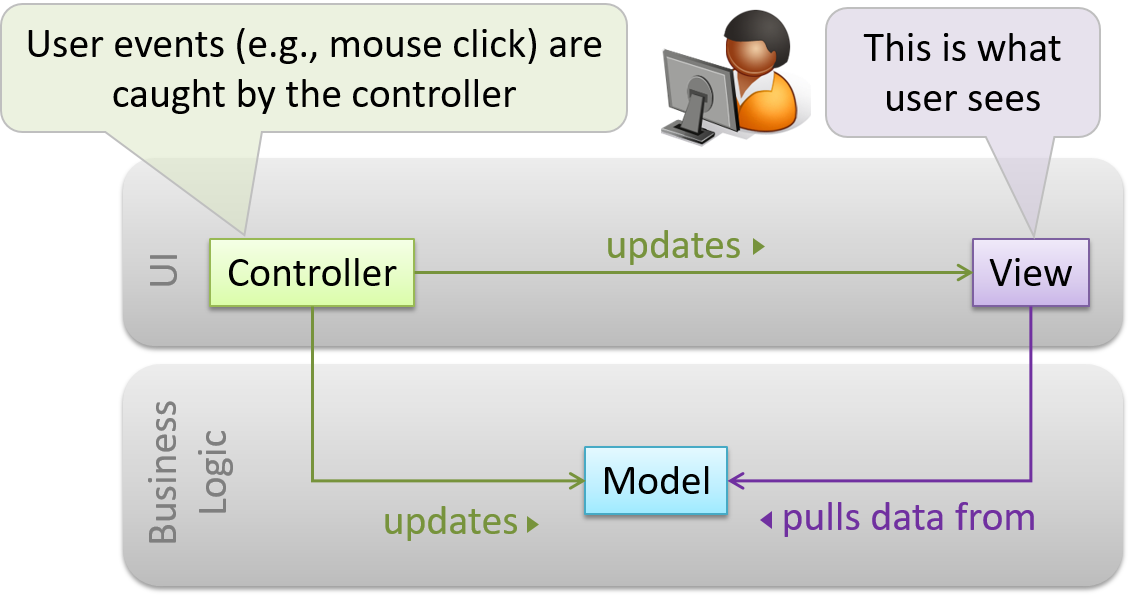
📦 Given below is a concrete example of MVC applied to a student management system. In this scenario, the user is retrieving data of one student.
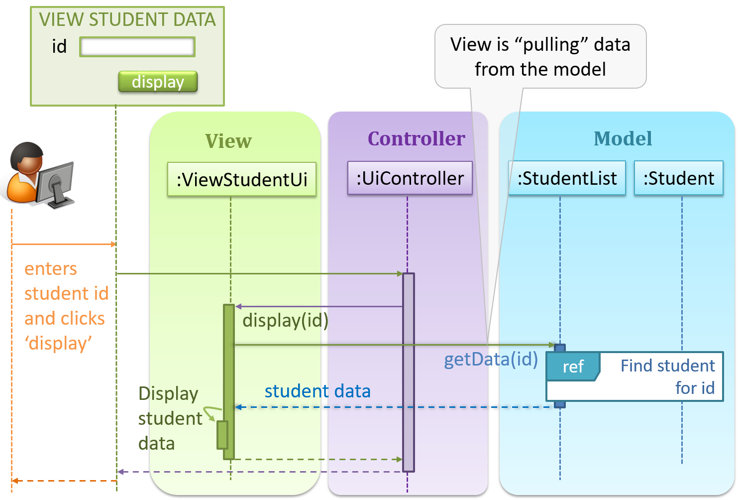
In the diagram above, when the user clicks on a button using the UI, the ‘click’ event is caught and handled by the UiController.
Note that in a simple UI where there’s only one view, Controller and View can be combined as one class.
There are many variations of the MVC model used in different domains. For example, the one used in a desktop GUI could be different from the one used in a Web application.
Observer Pattern
What
📦 Here is a scenario from the a student management system where the user is adding a new student to the system.
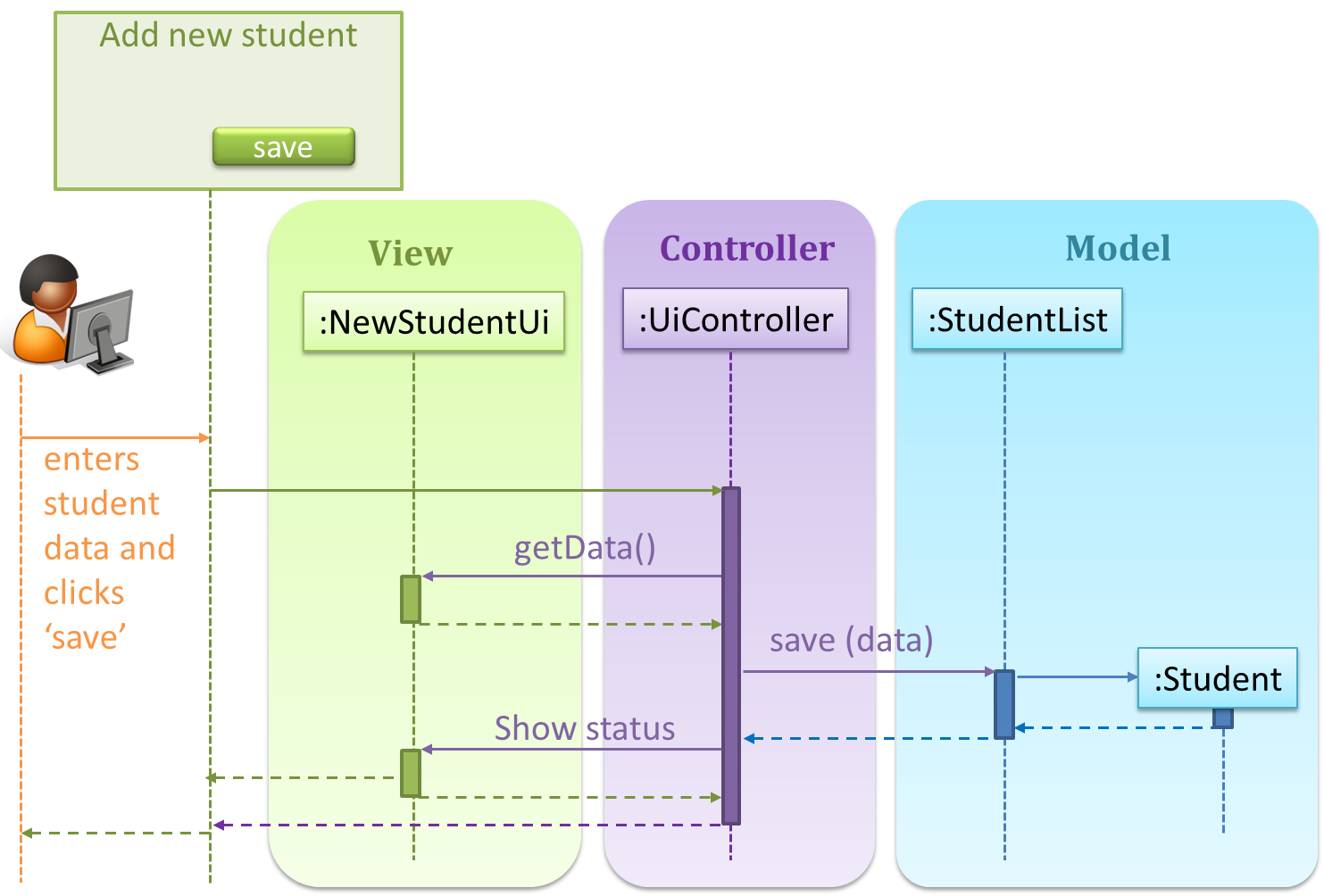
Now, assume the system has two additional views used in parallel by different users:
StudentListUi: that accesses a list of students andStudentStatsUi: that generates statistics of current students.
When a student is added to the database using NewStudentUi shown above, both StudentListUi and StudentStatsUi should get updated automatically, as shown below.
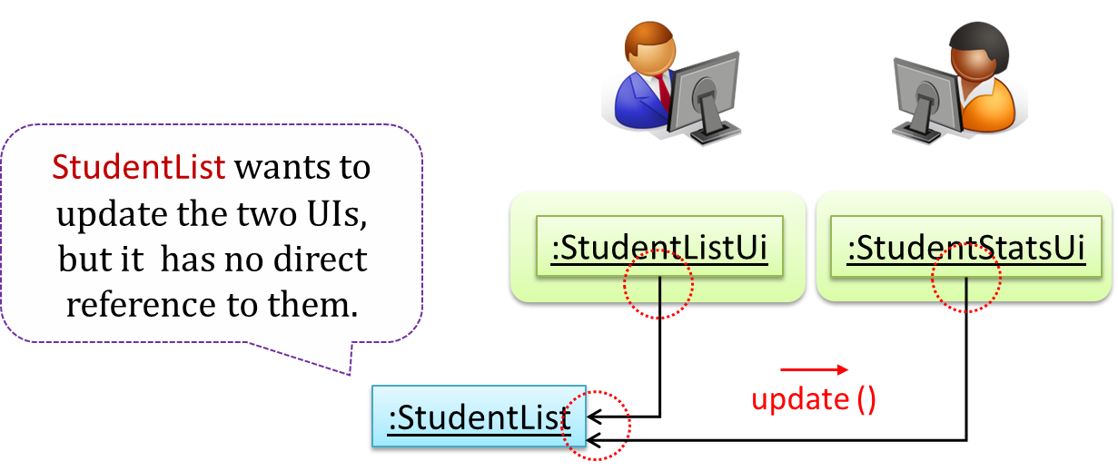
However, the StudentList object has no knowledge about StudentListUi and StudentStatsUi (note the direction of the navigability) and has no way to inform those objects. This is an example of the type
of problem addressed by the Observer pattern.
Context
An object (possibly, more than one) is interested to get notified when a change happens to another object. That is, some objects want to ‘observe’ another object.
Problem
The ‘observed’ object does not want to be coupled to objects that are ‘observing’ it.
Solution
Force the communication through an interface known to both parties.
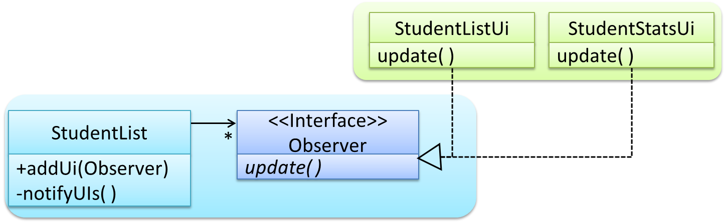
📦Here is the Observer pattern applied to the student management system.
During initialization of the system,
- First, create the relevant objects.
StudentList studentList = new StudentList();
StudentListUi listUi = new StudentListUi();
StudentStatusUi statusUi = new StudentStatsUi();
- Next, the two UIs indicate to the
StudentListthat they are interested in being updated wheneverStudentListchanges. This is also known as ‘subscribing for updates’.
studentList.addUi(listUi);
studentList.addUi(statusUi);
Within the addUi operation of StudentList, all Observer objects subscribers are added to an internal data structure called observerList.
//StudentList class
public void addUi(Observer o) {
    observerList.add(o);
}
As such, whenever the data in StudentList changes (e.g. when a new student is added to the StudentList), all interested observers are updated by calling the notifyUIs operation.
//StudentList class
public void notifyUIs() {
    for(Observer o: observerList) //for each observer in the list
        o.update();
}
UIs can then pull data from the StudentList whenever the update operation is called.
//StudentListUI class
public void update() {
    //refresh UI by pulling data from StudentList
}
Note that StudentList is unaware of the exact nature of the two UIs but still manages to communicate with them via an intermediary.
Here is the generic description of the observer pattern:
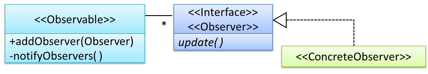
<< Observer >>is an interface: any class that implements it can observe an<< Observable >>. Any number of<< Observer >>objects can observe (i.e. listen to changes of) the<< Observable >>object.- The
<< Observable >>maintains a list of<< Observer >>objects.addObserver(Observer)operation adds a new<< Observer >>to the list of<< Observer >>s. - Whenever there is a change in the
<< Observable >>, thenotifyObservers()operation is called that will call theupdate()operation of all<< Observer >>sin the list.
In a GUI application, how is the Controller notified when the “save” button is clicked? UI frameworks such as JavaFX has inbuilt support for the Observer pattern.
More
Combining Design Patterns
Design patterns are usually embedded in a larger design and sometimes applied in combination with other design patterns.
📦 Let us look at a case study that shows how design patterns are used in the design of a class structure for a Stock Inventory System (SIS) for a shop. The shop sells appliances, and accessories for the appliances. SIS simply stores information about each item in the store.
Use Cases:
- Create a new item
- View information about an item
- Modify information about an item
- View all available accessories for a given appliance
- List all items in the store
SIS can be accessed using multiple terminals. Shop assistants use their own terminals to access SIS, while the shop manager’s terminal continuously displays a list of all items in store. In the future, it is expected that suppliers of items use their own applications to connect to SIS to get real-time information about current stock status. User authentication is not required for the current version, but may be required in the future.
A step by step explanation of the design is given below. Note that this is one out of many possible designs. Design patterns are also applied where appropriate.
A StockItem can be an Appliance or an Accessory.
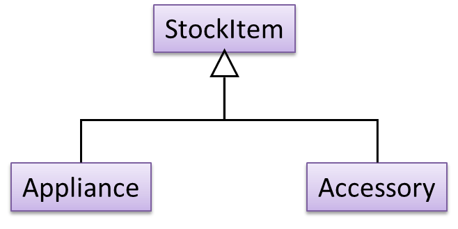
To track that each Accessory is associated with the correct Appliance, consider the following alternative class structures.
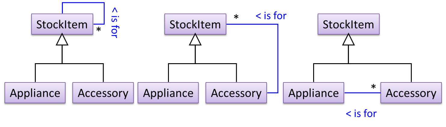
The third one seems more appropriate (the second one is suitable if accessories can have accessories). Next, consider between keeping a list of Appliances, and a list of StockItems. Which is more appropriate?
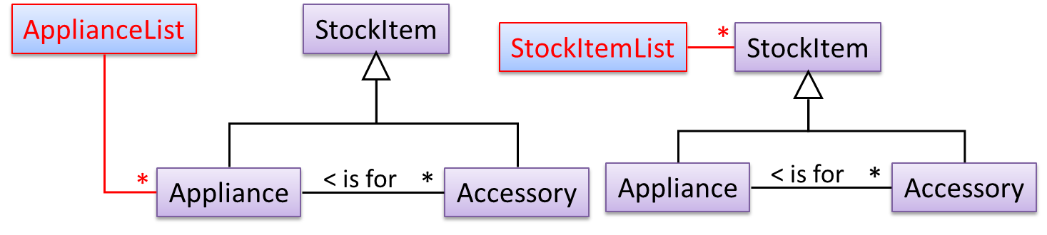
The latter seems more suitable because it can handle both appliances and accessories the same way. Next, an abstraction occurrence pattern is applied to keep track of StockItems.
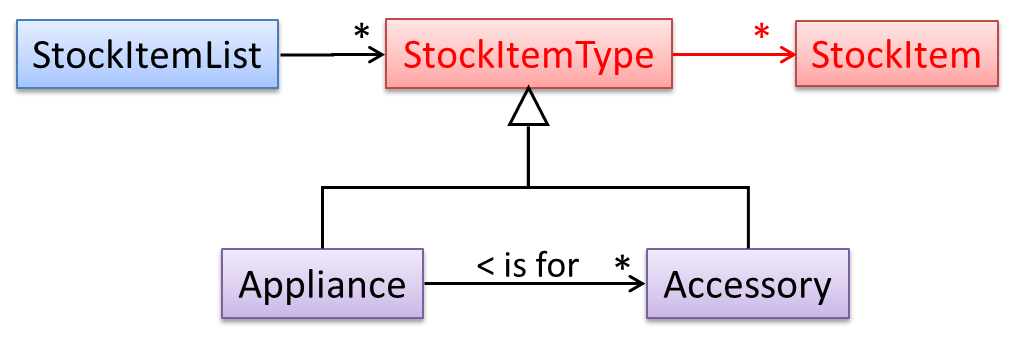
Note the inclusion of navigabilities. Here’s a sample object diagram based on the class model created thus far.
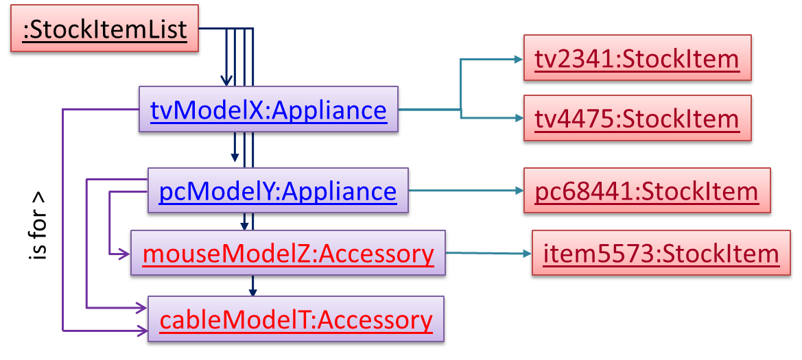
Next, apply the façade pattern to shield the SIS internals from the UI.
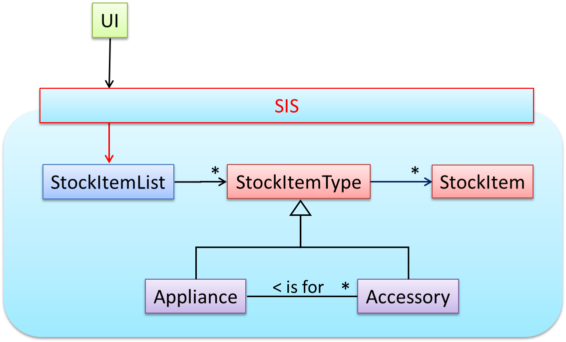
As UI consists of multiple views, the MVC pattern is applied here.
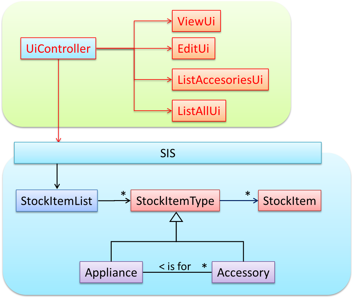
Some views need to be updated when the data change; apply the Observer pattern here.
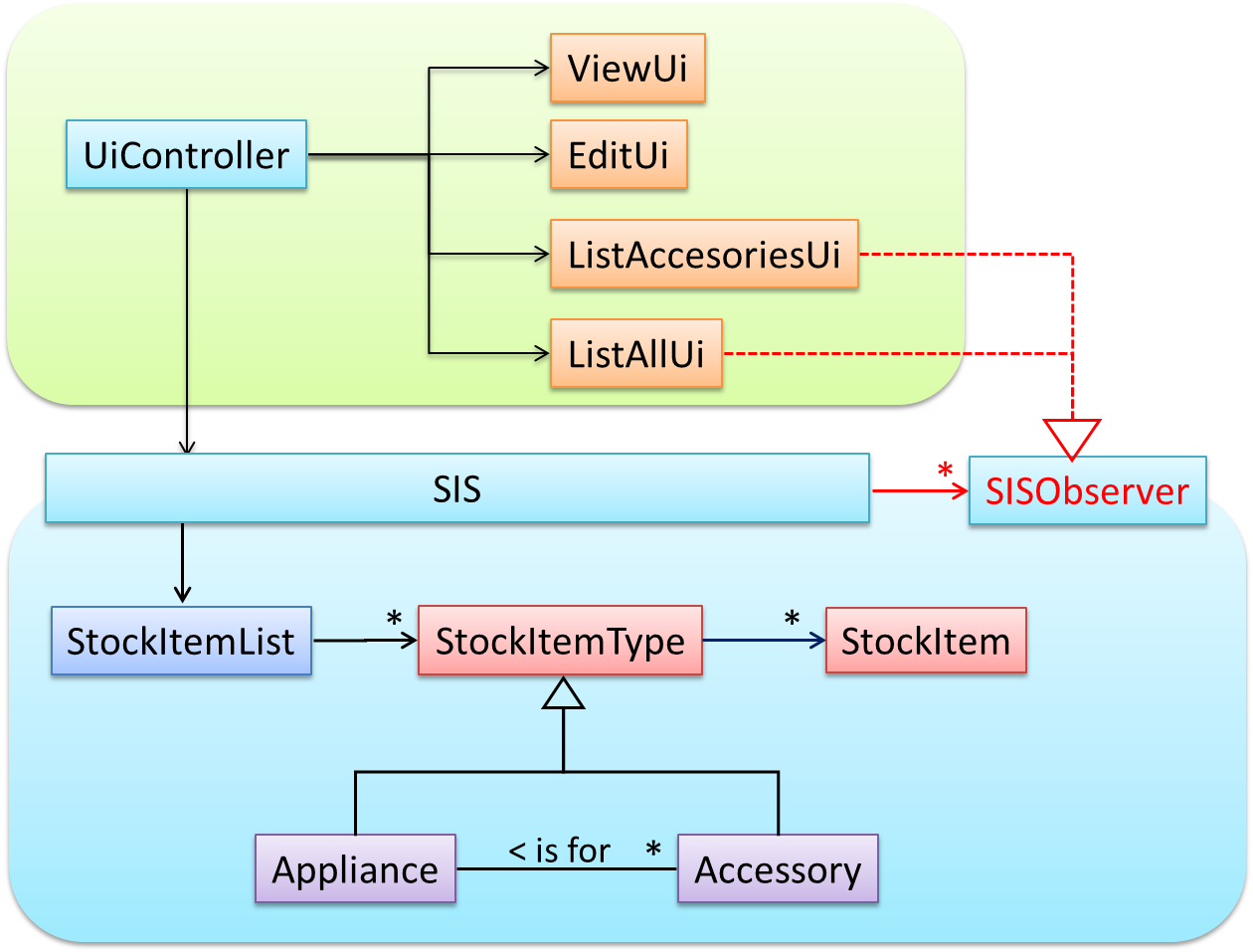
In addition, the Singleton pattern can be applied to the façade class.
Other Design Patterns
The most famous source of design patterns is the "Gang of Four" (GoF) book which contains 23 design patterns divided into three categories:
- Creational: About object creation. They separate the operation of an application from how its objects are created.
- Abstract Factory, Builder, Factory Method, Prototype, Singleton
- Structural: About the composition of objects into larger structures while catering for future extension in structure.
- Adapter, Bridge, Composite, Decorator, Façade, Flyweight, Proxy
- Behavioral: Defining how objects interact and how responsibility is distributed among them.
- Chain of Responsibility, Command, Interpreter, Template Method, Iterator, Mediator, Memento, Observer, State, Strategy, Visitor
Using Design Patterns
Design pattern provides a high-level vocabulary to talk about design.
📦 Someone can say 'apply Observer pattern here' instead of having to describe the mechanics of the solution in detail.
Knowing more patterns is a way to become more ‘experienced’. Aim to learn at least the context and the problem of patterns so that when you encounter those problems you know where to look for a solution.
Some patterns are domain-specific e.g. patterns for distributed applications, some are created in-house e.g. patterns in the company/project and some can be self-created e.g. from past experience.
Be careful not to overuse patterns. Do not throw patterns at a problem at every opportunity. Patterns come with overhead such as adding more classes or increasing the levels of abstraction. Use them only when they are needed. Before applying a pattern, make sure that:
- there is substantial improvement in the design, not just superficial.
- the associated tradeoffs are carefully considered. There are times when a design pattern is not appropriate (or an overkill).
Other Types of Patterns
The notion of capturing design ideas as "patterns" is usually attributed to Christopher Alexander. He is a building architect noted for his theories about design. His book Timeless way of building talks about "design patterns" for constructing buildings.
Here is a sample pattern from that book:
When a room has a window with a view, the window becomes a focal point: people are attracted to the window and want to look through it. The furniture in the room creates a second focal point: everyone is attracted toward whatever point the furniture aims them at (usually the center of the room or a TV). This makes people feel uncomfortable. They want to look out the window, and toward the other focus at the same time. If you rearrange the furniture, so that its focal point becomes the window, then everyone will suddenly notice that the room is much more “comfortable”
Apparently, patterns and anti-patterns are found in the field of building architecture. This is because they are general concepts applicable to any domain, not just software design. In software engineering, there are many general types of patterns: Analysis patterns, Design patterns, Testing patterns, Architectural patterns, Project management patterns, and so on.
In fact, the abstraction occurrence pattern is more of an analysis pattern than a design pattern, while MVC is more of an architectural pattern.
New patterns can be created too. If a common problem needs to be solved frequently that leads to a non-obvious and better solution, it can be formulated as a pattern so that it can be reused by others. However, don’t reinvent the wheel; the pattern might already exist.
Design Patterns vs Design Principles
Design principles have varying degrees of formality – rules, opinions, rules of thumb, observations, and axioms. Compared to design patterns, principles are more general, have wider applicability, with correspondingly greater overlap among them.
Design Approaches
Multi-Level Design
In a smaller system, design of the entire system can be shown in one place.
📦 This class diagram of se-edu/addressbook-level3 depicts the design of the entire software.

Design of bigger systems needs to be done/shown at multiple levels.
📦 This architecture diagram of se-edu/addressbook-level4 depicts the high-level design of the software.
Here are examples of lower level designs of some components of the same software:
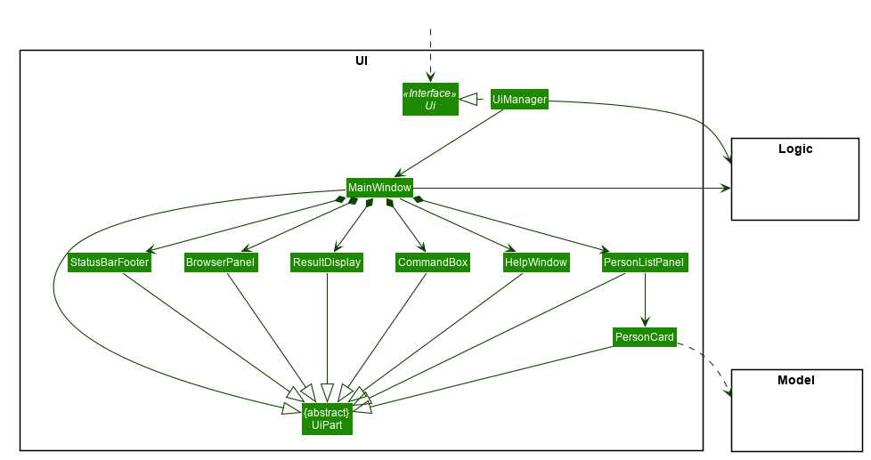
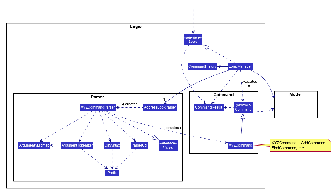
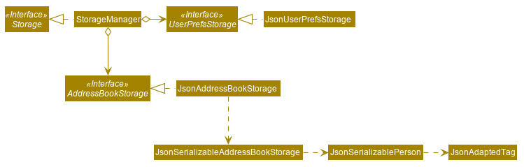
Top-Down and Bottom-Up Design
Multi-level design can be done in a top-down manner, bottom-up manner, or as a mix.
- Top-down: Design the high-level design first and flesh out the lower levels later. This is especially useful when designing big and novel systems where the high-level design needs to be stable before lower levels can be designed.
- Bottom-up: Design lower level components first and put them together to create the higher-level systems later. This is not usually scalable for bigger systems. One instance where this approach might work is when designing a variations of an existing system or re-purposing existing components to build a new system.
- Mix: Design the top levels using the top-down approach but switch to a bottom-up approach when designing the bottom levels.
Agile Design
Agile design can be contrasted with full upfront design in the following way:
Agile designs are emergent, they’re not defined up front. Your overall system design will emerge over time, evolving to fulfill new requirements and take advantage of new technologies as appropriate. Although you will often do some initial architectural modeling at the very beginning of a project, this will be just enough to get your team going. This approach does not produce a fully documented set of models in place before you may begin coding. -- adapted from agilemodeling.com
SECTION: IMPLEMENTATION
IDEs
Introduction
Professional software engineers often write code using Integrated Development Environments (IDEs). IDEs support all development-related work within the same tool.
An IDE generally consists of:
- A source code editor that includes features such as syntax coloring, auto-completion, easy code navigation, error highlighting, and code-snippet generation.
- A compiler and/or an interpreter (together with other build automation support) that facilitates the compilation/linking/running/deployment of a program.
- A debugger that allows the developer to execute the program one step at a time to observe the run-time behavior in order to locate bugs.
- Other tools that aid various aspects of coding e.g. support for automated testing, drag-and-drop construction of UI components, version management support, simulation of the target runtime platform, and modeling support.
Examples of popular IDEs:
- Java: Eclipse, Intellij IDEA, NetBeans
- C#, C++: Visual Studio
- Swift: XCode
- Python: PyCharm
Some Web-based IDEs have appeared in recent times too e.g., Amazon's Cloud9 IDE.
Some experienced developers, in particular those with a UNIX background, prefer lightweight yet powerful text editors with scripting capabilities (e.g. Emacs) over heavier IDEs.
Debugging
What
Debugging is the process of discovering defects in the program. Here are some approaches to debugging:
-
👎 By inserting temporary print statements: This is an ad-hoc approach in which print statements are inserted in the program to print information relevant to debugging, such as variable values. e.g.
Exiting process() method, x is 5.347. This approach is not recommended due to these reasons.- Incurs extra effort when inserting and removing the print statements.
- Unnecessary program modifications increases the risk of introducing errors into the program.
- These print statements, if not promptly removed, may even appear unexpectedly in the production version.
-
👎 By manually tracing through the code: Otherwise known as ‘eye-balling’, this approach doesn't have the cons of the previous approach, but it too is not recommended (other than as a 'quick try') due to these reasons:
- It is difficult, time consuming, and error-prone technique.
- If you didn't spot the error while writing code, you might not spot the error when reading code too.
-
👍 Using a debugger: A debugger tool allows you to pause the execution, then step through one statement at a time while examining the internal state if necessary. Most IDEs come with an inbuilt debugger. This is the recommended approach for debugging.
Code Quality
Introduction
Basic
Always code as if the person who ends up maintaining your code will be a violent psychopath who knows where you live. -- Martin Golding
Guideline: Maximise Readability
Introduction
Programs should be written and polished until they acquire publication quality. --Niklaus Wirth
Among various dimensions of code quality, such as run-time efficiency, security, and robustness, one of the most important is understandability. This is because in any non-trivial software project, code needs to be read, understood, and modified by other developers later on. Even if we do not intend to pass the code to someone else, code quality is still important because we all become 'strangers' to our own code someday.
Example: The two code samples given below achieve the same functionality, but one is easier to read.

int subsidy() {
    int subsidy;
    if (!age) {
        if (!sub) {
            if (!notFullTime) {
                subsidy = 500;
            } else {
                subsidy = 250;
            }
        } else {
            subsidy = 250;
        }
    } else {
        subsidy = -1;
    }
    return subsidy;
}

int calculateSubsidy() {
    int subsidy;
    if (isSenior) {
        subsidy = REJECT_SENIOR;
    } else if (isAlreadySubsidised) {
        subsidy = SUBSIDISED_SUBSIDY;
    } else if (isPartTime) {
        subsidy = FULLTIME_SUBSIDY * RATIO;
    } else {
        subsidy = FULLTIME_SUBSIDY;
    }
    return subsidy;
}
Basic
Be wary when a method is longer than the computer screen, and take corrective action when it goes beyond 30 LOC (lines of code). The bigger the haystack, the harder it is to find a needle.
If you need more than 3 levels of indentation, you're screwed anyway, and should fix your program. --Linux 1.3.53 CodingStyle
In particular, avoid arrowhead style code.
Example:
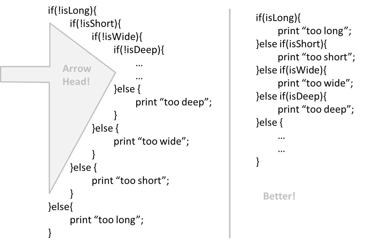
Avoid complicated expressions, especially those having many negations and nested parentheses. If you must evaluate complicated expressions, have it done in steps (i.e. calculate some intermediate values first and use them to calculate the final value).
Example:
return ((length < MAX_LENGTH) || (previousSize != length)) && (typeCode == URGENT);
boolean isWithinSizeLimit = length < MAX_LENGTH;
boolean isSameSize = previousSize != length;
boolean isValidCode = isWithinSizeLimit || isSameSize;

boolean isUrgent = typeCode == URGENT;

return isValidCode && isUrgent;
The competent programmer is fully aware of the strictly limited size of his own skull; therefore he approaches the programming task in full humility, and among other things he avoids clever tricks like the plague. -- Edsger Dijkstra
When the code has a number that does not explain the meaning of the number, we call that a magic number (as in “the number appears as if by magic”).
Example:
|
|
|---|---|
return 3.14236; |
return PI |
return 9 |
return MAX_SIZE-1 |
Using a named constant makes the code easier to understand because the name tells us more about the meaning of the number. Similarly, we can have ‘magic’ values of other data types.
return “Error 1432”; // A magic string!
Make the code as explicit as possible, even if the language syntax allows them to be implicit. Here are some examples:
- Use explicit type conversion instead of implicit type conversion.
- Use parentheses/braces to show grouping even when they can be skipped.
- Use enumerations when a certain variable can take only a small number of finite values. For example, instead of declaring the variable 'state' as an integer and using values 0,1,2 to denote the states 'starting', 'enabled', and 'disabled'
respectively, declare 'state' as type
SystemStateand define an enumerationSystemStatethat has values'STARTING','ENABLED', and'DISABLED'. - When statements should follow a particular order, try to make it obvious (with appropriate naming, or at least comments). For example, if you name two functions
'taskA()'and'taskB()', it is not obvious which one should be called first. Contrast this with naming the functions'phaseOne()'and'phaseTwo()'instead. This is especially important when statements in one function must be called before the other one.
Intermediate
Lay out the code so that it adheres to the logical structure. The code should read like a story. Just like we use section breaks, chapters and paragraphs to organize a story, use classes, methods, indentation and line spacing in your code to group related segments of the code. For example, you can use blank lines to group related statements together. Sometimes, the correctness of your code does not depend on the order in which you perform certain intermediary steps. Nevertheless, this order may affect the clarity of the story you are trying to tell. Choose the order that makes the story most readable.
Avoid things that would make the reader go ‘huh?’, such as,
- unused parameters in the method signature
- similar things look different
- different things that look similar
- multiple statements in the same line
- data flow anomalies such as, pre-assigning values to variables and modifying it without any use of the pre-assigned value
As the old adage goes, "keep it simple, stupid” (KISS). Do not try to write ‘clever’ code. For example, do not dismiss the brute-force yet simple solution in favor of a complicated one because of some ‘supposed benefits’ such as 'better reusability' unless you have a strong justification.
Debugging is twice as hard as writing the code in the first place. Therefore, if you write the code as cleverly as possible, you are, by definition, not smart enough to debug it. --Brian W. Kernighan
Programs must be written for people to read, and only incidentally for machines to execute. --Abelson and Sussman
Optimizing code prematurely has several drawbacks:
- We may not know which parts are the real performance bottlenecks. This is especially the case when the code undergoes transformations (e.g. compiling, minifying, transpiling, etc.) before it becomes an executable. Ideally, you should use a profiler tool to identify the actual bottlenecks of the code first, and optimize only those parts.
- Optimizing can complicate the code, affecting correctness and understandability
- Hand-optimized code can be harder for the compiler to optimize (the simpler the code, the easier for the compiler to optimize it). In many cases a compiler can do a better job of optimizing the runtime code if you don't get in the way by trying to hand-optimize the source code.
A popular saying in the industry is make it work, make it right, make it fast which means in most cases getting the code to perform correctly should take priority over optimizing it. If the code doesn't work correctly, it has no value on matter how fast/efficient it it.
Premature optimization is the root of all evil in programming. --Donald Knuth
Note that there are cases where optimizing takes priority over other things e.g. when writing code for resource-constrained environments. This guideline simply a caution that you should optimize only when it is really needed.
Avoid varying the level of
Example:
readData();
salary = basic*rise+1000;
tax = (taxable?salary*0.07:0);
displayResult();
readData();
processData();
displayResult();
Design → Design Fundamentals → Abstraction →
What
Abstraction is a technique for dealing with complexity. It works by establishing a level of complexity (or an aspect) we are interested in, and suppressing the more complex details below that level (or irrelevant to that aspect).
Most programs are written to solve complex problems involving large amounts of intricate details. It is impossible to deal with all these details at the same time. The guiding principle of abstraction stipulates that we capture only details that are relevant to the current perspective or the task at hand.
Ignoring lower level data items and thinking in terms of bigger entities is called data abstraction.
📦 Within a certain software component, we might deal with a user data type, while ignoring the details contained in the user data item such as name, and date of birth. These details have been ‘abstracted away’ as they do not affect the task of that software component.
Control abstraction abstracts away details of the actual control flow to focus on tasks at a simplified level.
📦 print(“Hello”) is an abstraction of the actual output mechanism within the computer.
Abstraction can be applied repeatedly to obtain progressively higher levels of abstractions.
📦 An example of different levels of data abstraction: a File is a data item that is at a higher level than an array and an array is at a higher level than a bit.
📦 An example of different levels of control abstraction: execute(Game) is at a higher level than print(Char) which is at a higher than an Assembly language instruction MOV.
Advanced
The happy path (i.e. the execution path taken when everything goes well) should be clear and prominent in your code. Restructure the code to make the happy path unindented as much as possible. It is the ‘unusual’ cases that should be indented. Someone reading the code should not get distracted by alternative paths taken when error conditions happen. One technique that could help in this regard is the use of guard clauses.
Example:
if (!isUnusualCase) {  //detecting an unusual condition
    if (!isErrorCase) {
        start();    //main path
        process();
        cleanup();
        exit();
    } else {
        handleError();
    }
} else {
    handleUnusualCase(); //handling that unusual condition
}
In the code above,
- Unusual condition detection is separated from their handling.
- Main path is nested deeply.
if (isUnusualCase) { //Guard Clause
    handleUnusualCase();
    return;
}

if (isErrorCase) { //Guard Clause
    handleError();
    return;
}

start();
process();
cleanup();
exit();
In contrast, the above code
- deals with unusual conditions as soon as they are detected so that the reader doesn't have to remember them for long.
- keeps the main path un-indented.
Guideline: Follow a Standard
Introduction
One essential way to improve code quality is to follow a consistent style. That is why software engineers follow a strict coding standard (aka style guide).
The aim of a coding standard is to make the entire code base look like it was written by one person. A coding standard is usually specific to a programming language and specifies guidelines such as the location of opening and closing braces, indentation styles and naming styles (e.g. whether to use Hungarian style, Pascal casing, Camel casing, etc.). It is important that the whole team/company use the same coding standard and that standard is not generally inconsistent with typical industry practices. If a company's coding standards is very different from what is used typically in the industry, new recruits will take longer to get used to the company's coding style.
IDEs can help to enforce some parts of a coding standard e.g. indentation rules.
Basic
Go through the provided Java coding standard and learn the basic style rules.
Intermediate
Go through the provided Java coding standard and learn the intermediate style rules.
Guideline: Name Well
Introduction
Proper naming improves the readability. It also reduces bugs caused by ambiguities regarding the intent of a variable or a method.
There are only two hard things in Computer Science: cache invalidation and naming things. -- Phil Karlton
Basic
Use nouns for classes/variables and verbs for methods/functions.
Examples:
| Name for a | |
|
|---|---|---|
| Class | CheckLimit |
LimitChecker |
| method | result() |
calculate() |
Distinguish clearly between single valued and multivalued variables.
Examples:
Person student
ArrayList<Person> students
Use correct spelling in names. Avoid 'texting-style' spelling. Avoid foreign language words, slang, and names that are only meaningful within specific contexts/times e.g. terms from private jokes, a TV show currently popular in your country
Intermediate
A name is not just for differentiation; it should explain the named entity to the reader accurately and at a sufficient level of detail.
Examples:
|
|
|---|---|
processInput() (what 'process'?) |
removeWhiteSpaceFromInput() |
flag |
isValidInput |
temp |
If the name has multiple words, they should be in a sensible order.
Examples:
|
|
|---|---|
bySizeOrder() |
orderBySize() |
Imagine going to the doctor's and saying "My eye1 is swollen"! Don’t use numbers or case to distinguish names.
Examples:
|
|
|
|---|---|---|
value1, value2 |
value, Value |
originalValue, finalValue |
While it is preferable not to have lengthy names, names that are 'too short' are even worse. If you must abbreviate or use acronyms, do it consistently. Explain their full meaning at an obvious location.
Related things should be named similarly, while unrelated things should NOT.
Example: Consider these variables
colorBlack: hex value for color blackcolorWhite: hex value for color whitecolorBlue: number of times blue is usedhexForRed: : hex value for color red
This is misleading because colorBlue is named similar to colorWhite and colorBlack but has a different purpose while hexForRed is named differently but has very similar purpose to the
first two variables. The following is better:
hexForBlackhexForWhitehexForRedblueColorCount
Avoid misleading or ambiguous names (e.g. those with multiple meanings), similar sounding names, hard-to-pronounce ones (e.g. avoid ambiguities like "is that a lowercase L, capital I or number 1?", or "is that number 0 or letter O?"), almost similar names.
Examples:
|
|
Reason |
|---|---|---|
phase0 |
phaseZero |
Is that zero or letter O? |
rwrLgtDirn |
rowerLegitDirection |
Hard to pronounce |
right left wrong |
rightDirection leftDirection wrongResponse |
right is for 'correct' or 'opposite of 'left'? |
redBooks readBooks |
redColorBooks booksRead |
red and read (past tense) sounds the same |
FiletMignon |
egg |
If the requirement is just a name of a food, egg is a much easier to type/say choice than FiletMignon |
Guideline: Avoid Unsafe Shortcuts
Introduction
It is safer to use language constructs in the way they are meant to be used, even if the language allows shortcuts. Some such coding practices are common sources of bugs. Know them and avoid them.
Basic
Always include a default branch in case statements.
Furthermore, use it for the intended default action and not just to execute the last option. If there is no default action, you can use the 'default' branch to detect errors (i.e. if execution reached the default branch, throw
an exception). This also applies to the final else of an if-else construct. That is, the final else should mean 'everything else', and not the final option. Do not use else when an
if condition can be explicitly specified, unless there is absolutely no other possibility.
if (red) print "red";
else print "blue";
if (red) print "red";
else if (blue) print "blue";
else error("incorrect input");
- Use one variable for one purpose. Do not reuse a variable for a different purpose other than its intended one, just because the data type is the same.
- Do not reuse formal parameters as local variables inside the method.
double computeRectangleArea(double length, double width) {
    length = length * width;
    return length;
}
double computeRectangleArea(double length, double width) {
    double area;
    area = length * width;
    return area;
}
Never write an empty catch statement. At least give a comment to explain why the catch block is left empty.
We all feel reluctant to delete code we have painstakingly written, even if we have no use for that code any more ("I spent a lot of time writing that code; what if we need it again?"). Consider all code as baggage you have to carry; get rid of unused code the moment it becomes redundant. If you need that code again, simply recover it from the revision control tool you are using. Deleting code you wrote previously is a sign that you are improving.
Intermediate
Minimize global variables. Global variables may be the most convenient way to pass information around, but they do create implicit links between code segments that use the global variable. Avoid them as much as possible.
Define variables in the least possible scope. For example, if the variable is used only within the if block of the conditional statement, it should be declared inside that if block.
The most powerful technique for minimizing the scope of a local variable is to declare it where it is first used. -- Effective Java, by Joshua Bloch
📎 Resources:
Code duplication, especially when you copy-paste-modify code, often indicates a poor quality implementation. While it may not be possible to have zero duplication, always think twice before duplicating code; most often there is a better alternative.
This guideline is closely related to the
Supplmentary → Principles →
DRY Principle
DRY (Don't Repeat Yourself) Principle: Every piece of knowledge must have a single, unambiguous, authoritative representation within a system The Pragmatic Programmer, by Andy Hunt and Dave Thomas
This principle guards against duplication of information.
📦 The functionality implemented twice is a violation of the DRY principle even if the two implementations are different.
📦 The value a system-wide timeout being defined in multiple places is a violation of DRY.
Guideline: Comment Minimally, But Sufficiently
Introduction
Good code is its own best documentation. As you’re about to add a comment, ask yourself, ‘How can I improve the code so that this comment isn’t needed?’ Improve the code and then document it to make it even clearer. --Steve McConnell, Author of Clean Code
Some think commenting heavily increases the 'code quality'. This is not so. Avoid writing comments to explain bad code. Improve the code to make it self-explanatory.
Basic
If the code is self-explanatory, refrain from repeating the description in a comment just for the sake of 'good documentation'.
// increment x
x++;

//trim the input
trimInput();
Do not write comments as if they are private notes to self. Instead, write them well enough to be understood by another programmer. One type of comments that is almost always useful is the header comment that you write for a class or an operation to explain its purpose.
Reason: this comment will only make sense to the person who wrote it
// a quick trim function used to fix bug I detected overnight
void trimInput(){
    ....
}
/** Trims the input of leading and trailing spaces */
void trimInput(){
    ....
}
Intermediate
Comments should explain what and why aspect of the code, rather than the how aspect.
👍 What : The specification of what the code supposed to do. The reader can compare such comments to the implementation to verify if the implementation is correct
📦 Example: This method is possibly buggy because the implementation does not seem to match the comment. In this case the comment could help the reader to detect the bug.
/** Removes all spaces from the {@code input} */
void compact(String input){
    input.trim();
}
👍 Why : The rationale for the current implementation.
📦 Example: Without this comment, the reader will not know the reason for calling this method.
// Remove spaces to comply with IE23.5 formatting rules
compact(input);
👎 How : The explanation for how the code works. This should already be apparent from the code, if the code is self-explanatory. Adding comments to explain the same thing is redundant.
📦 Example:
Reason: Comment explains how the code works.
// return true if both left end and right end are correct or the size has not incremented
return (left && right) || (input.size() == size);
Reason: Code refactored to be self-explanatory. Comment no longer needed.
boolean isSameSize = (input.size() == size) ;
return (isLeftEndCorrect && isRightEndCorrect) || isSameSize;
Refactoring
What
The first version of the code you write may not be of production quality. It is OK to first concentrate on making the code work, rather than worry over the quality of the code, as long as you improve the quality later. This process of improving a program's internal structure in small steps without modifying its external behavior is called refactoring.
- Refactoring is not rewriting: Discarding poorly-written code entirely and re-writing it from scratch is not refactoring because refactoring needs to be done in small steps.
- Refactoring is not bug fixing: By definition, refactoring is different from bug fixing or any other modifications that alter the external behavior (e.g. adding a feature) of the component in concern.
💡 Improving code structure can have many secondary benefits: e.g.
- hidden bugs become easier to spot
- improve performance (sometimes, simpler code runs faster than complex code because simpler code is easier for the compiler to optimize).
Given below are two common refactorings (taken from
http://refactoring.com/catalog/ - This is a list of common refactorings, maintained by Martin Fowler, a leading authority on refactoring. He is also the author of the ‘bestseller’ on refactoring: Refactoring: Improving the Design of Existing Code
Refactoring Name: Consolidate Duplicate Conditional Fragments
Situation: The same fragment of code is in all branches of a conditional expression.
Method: Move it outside of the expression.
Example:
if (isSpecialDeal()) {
    total = price * 0.95;
    send();
} else {
    total = price * 0.98;
    send();
}
⤵️
if (isSpecialDeal()){
    total = price * 0.95;
} else {
    total = price * 0.98;
}
send();
Refactoring Name: Extract Method
Situation: You have a code fragment that can be grouped together.
Method: Turn the fragment into a method whose name explains the purpose of the method.
Example:
void printOwing() {
    printBanner();

    //print details
    System.out.println("name:	" + name);
    System.out.println("amount	" + getOutstanding());
}
⤵️
void printOwing() {
    printBanner();
    printDetails(getOutstanding());
}

void printDetails (double outstanding) {
    System.out.println("name:	" + name);
    System.out.println("amount	" + outstanding);
}
💡 Some IDEs have built in support for basic refactorings such as automatically renaming a variable/method/class in all places it has been used.
Important: Refactoring, even if done with the aid of an IDE, may still result in regressions. Therefore, each small refactoring should be followed by regression testing.
How
Given below are some more commonly used refactorings. A more comprehensive list is available at
http://refactoring.com/catalog/ - This is a list of common refactorings, maintained by Martin Fowler, a leading authority on refactoring. He is also the author of the ‘bestseller’ on refactoring: Refactoring: Improving the Design of Existing Code
When
We know that it is important to refactor frequently so as to avoid the accumulation of ‘messy’ code which might get out of control. But how much refactoring is too much refactoring? It is too much refactoring when the benefits no longer justify the cost. The costs and the benefits depend on the context. That is why some refactorings are ‘opposites’ of each other (e.g. extract method vs inline method).
Documentation
Introduction
What
Developer-to-developer documentation can be in one of two forms:
- Documentation for developer-as-user: Software components are written by developers and reused by other developers, which means there is a need to document how such components are to be used. Such documentation can
take several forms:
- API documentation: APIs expose functionality in small-sized, independent and easy-to-use chunks, each of which can be documented systematically.
- Tutorial-style instructional documentation: In addition to explaining functions/methods independently, some higher-level explanations of how to use an API can be useful.
- 📦 Example of API Documentation: String API.
- 📦 Example of tutorial-style documentation: Java Intenatioanalization Tutorial
- 📦 Example of API Documentation: string API.
- 📦 Example of tutorial-style documentation: How to use Regular Expressions in Python
- Documentation for developer-as-maintainer: There is a need to document how a system or a component is designed, implemented and tested so that other developers can maintain and evolve the code. Writing documentation of this type is harder because of the need to explain complex internal details. However, given that readers of this type of documentation usually have access to the source code itself, only some information need to be included in the documentation, as code (and code comments) can also serve as a complementary source of information.
- 📦 An example: se-edu/addressbook-level4 Developer Guide.
Guidelines
Guideline: Go Top-down, Not Bottom-up
What
When writing project documents, a top-down breadth-first explanation is easier to understand than a bottom-up one.
Why
The main advantage of the top-down approach is that the document is structured like an upside down tree (root at the top) and the reader can travel down a path she is interested in until she reaches the component she is interested to learn in-depth, without having to read the entire document or understand the whole system.
How
📦 To explain a system called SystemFoo with two sub-systems, FrontEnd and BackEnd, start by describing the system at the highest level of abstraction, and progressively drill down to lower level details.
An outline for such a description is given below.
[First, explain what the system is, in a black-box fashion (no internal details, only the external view).]
SystemFoois a ....
[Next, explain the high-level architecture of SystemFoo, referring to its major components only.]
SystemFooconsists of two major components:FrontEndandBackEnd.
The job ofFrontEndis to ... while the job ofBackEndis to ...
And this is howFrontEndandBackEndwork together ...
[Now we can drill down to FrontEnd's details.]
FrontEndconsists of three major components:A,B,C
A's job is to ...B's job is to...C's job is to...
And this is how the three components work together ...
[At this point, further drill down the internal workings of each component. A reader who is not interested in knowing nitty-gritty details can skip ahead to the section on BackEnd.]
In-depth description of
A
In-depth description ofB
...
[At this point drill down details of the BackEnd.]
...
Guideline: Aim for Comprehensibility
What
Technical documents exist to help others understand technical details. Therefore, it is not enough for the documentation to be accurate and comprehensive, it should also be comprehensible too.
How
Here are some tips on writing effective documentation.
- Use plenty of diagrams: It is not enough to explain something in words; complement it with visual illustrations (e.g. a UML diagram).
- Use plenty of examples: When explaining algorithms, show a running example to illustrate each step of the algorithm, in parallel to worded explanations.
- Use simple and direct explanations: Convoluted explanations and fancy words will annoy readers. Avoid long sentences.
- Get rid of statements that do not add value: For example, 'We made sure our system works perfectly' (who didn't?), 'Component X has its own responsibilities' (of course it has!).
- It is not a good idea to have separate sections for each type of artifact, such as 'use cases', 'sequence diagrams', 'activity diagrams', etc. Such a structure, coupled with the indiscriminate inclusion of diagrams without justifying their need, indicates a failure to understand the purpose of documentation. Include diagrams when they are needed to explain something. If you want to provide additional diagrams for completeness' sake, include them in the appendix as a reference.
Guideline: Document Minimally, but Sufficiently
What
Aim for 'just enough' developer documentation.
- Writing and maintaining developer documents is an overhead. You should try to minimize that overhead.
- If the readers are developers who will eventually read the code, the documentation should complement the code and should provide only just enough guidance to get started.
How
Anything that is already clear in the code need not be described in words. Instead, focus on providing higher level information that is not readily visible in the code or comments.
Refrain from duplicating chunks or text. When describing several similar algorithms/designs/APIs, etc., do not simply duplicate large chunks of text. Instead, describe the similarity in one place and emphasize only the differences in other places. It is very annoying to see pages and pages of similar text without any indication as to how they differ from each other.
Tools
JavaDoc
What
Javadoc is a tool for generating API documentation in HTML format from doc comments in source. In addition, modern IDEs use JavaDoc comments to generate explanatory tool tips.
📦 An example method header comment in JavaDoc format (adapted from Oracle's Java documentation)
/**
 * Returns an Image object that can then be painted on the screen.
 * The url argument must specify an absolute {@link URL}. The name
 * argument is a specifier that is relative to the url argument.
 * <p>
 * This method always returns immediately, whether or not the
 * image exists. When this applet attempts to draw the image on
 * the screen, the data will be loaded. The graphics primitives
 * that draw the image will incrementally paint on the screen.
 *
 * @param url an absolute URL giving the base location of the image
 * @param name the location of the image, relative to the url argument
 * @return the image at the specified URL
 * @see Image
 */
 public Image getImage(URL url, String name) {
        try {
            return getImage(new URL(url, name));
        } catch (MalformedURLException e) {
            return null;
        }
 }
📦 Generated HTML documentation:
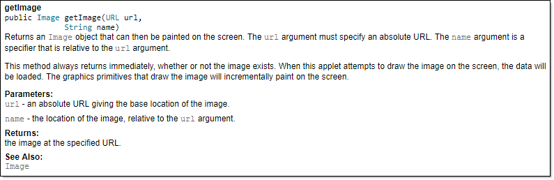
📦 Tooltip generated by Intellij IDE:
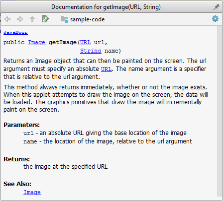
Markdown
What
Markdown is a lightweight markup language with plain text formatting syntax.
AsciiDoc
What
AsciiDoc is similar to Markdown but has more powerful (but also more complex) syntax.
Error Handling
Introduction
What
Well-written applications include error-handling code that allows them to recover gracefully from unexpected errors. When an error occurs, the application may need to request user intervention, or it may be able to recover on its own. In extreme cases, the application may log the user off or shut down the system. --(source)
Exceptions
What
Exceptions are used to deal with 'unusual' but not entirely unexpected situations that the program might encounter at run time.
Exception:
An exception is an event, which occurs during the execution of a program, that disrupts the normal flow of the program's instructions. –- Java Tutorial (Oracle Inc.)
📦 Examples:
- A network connection encounters a timeout due to a slow server.
- The code tries to read a file from the hard disk but the file is corrupted and cannot be read.
How
Most languages allow a method to encapsulate the unusual situation in an Exception object and 'throw'/'raise' that object so that another piece of code can 'catch' it and deal with it. This is especially useful when code segment that encountered the unusual situation does not know how to deal with it.
Exception objects can propagate up the method/function call hierarchy until it is dealt with. Usually, an exception thrown by a method is caught by the caller method. If the called method does not know how to deal with the exception it caught, it can throw/raise the Exception object to its own caller. If none of the callers is prepared to deal with the exception, the exceptions can propagate through the method call stack until it is received by the main method and thrown to the runtime, thus halting the system.
📦 In the code given below, processArray can potentially throw an InvalidInputException. Because of that, processInput method invokes processArray method inside a try{ } block and has a catch{ } block to specify what to do if the exception is actually thrown.
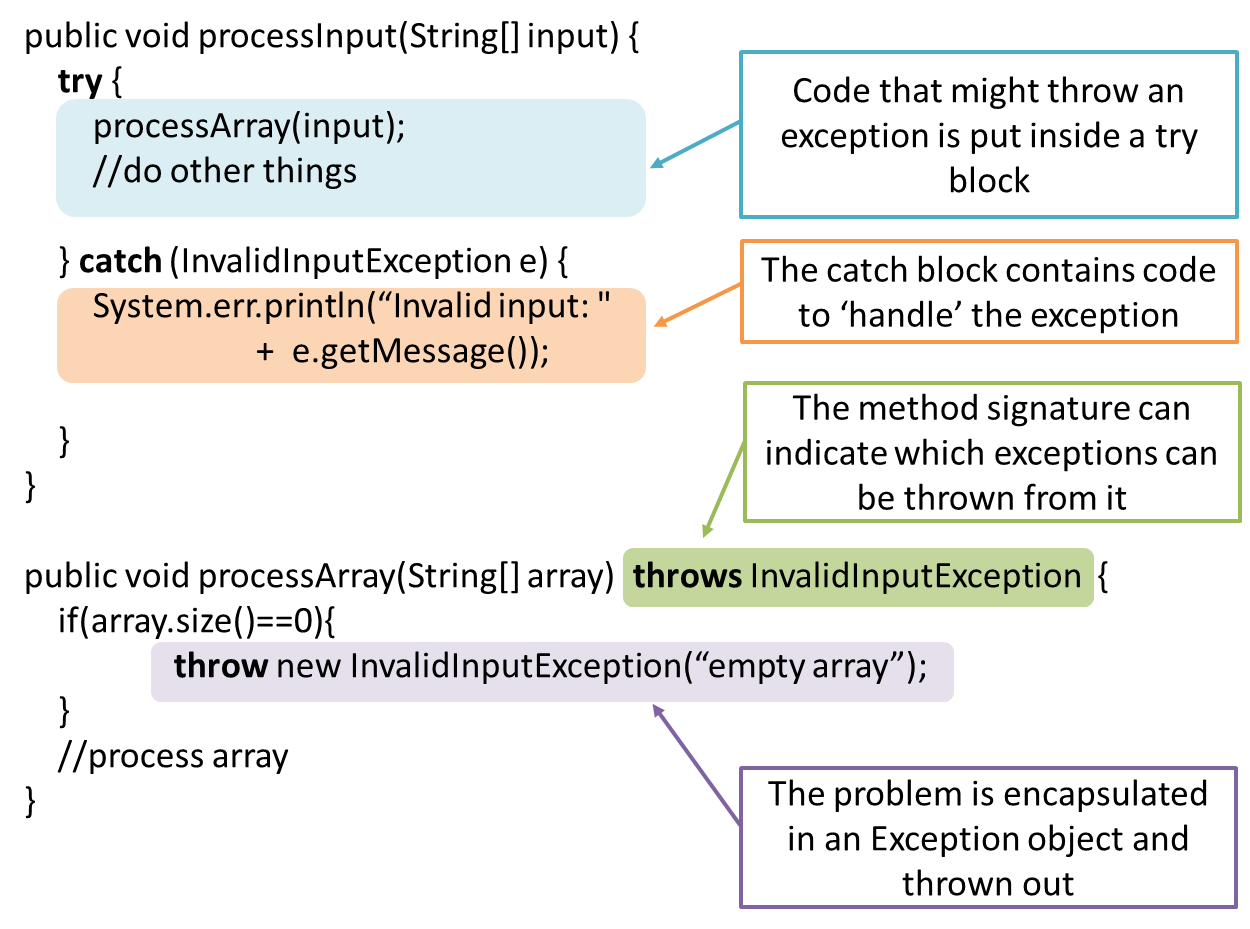
📦 In the code given below, process_array function can potentially raise a ValueError exception. Because of that, process_input function invokes process_array function inside a try clause and has a except clause to specify what to do if the exception is actually raised.
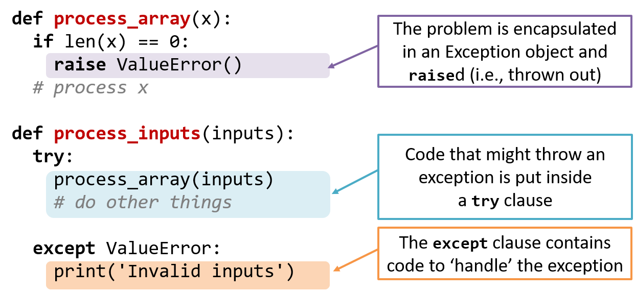
Advantages of exception handling in this way:
- The ability to propagate error information through the call stack.
- The separation of code that deals with 'unusual' situations from the code that does the 'usual' work.
When
In general, use exceptions only for 'unusual' conditions. Use normal return statements to pass control to the caller for conditions that are 'normal'.
Assertions
What
Assertions are used to define assumptions about the program state so that the runtime can verify them. An assertion failure indicates a possible bug in the code because the code has resulted in a program state that violates an assumption about how the code should behave.
📦 An assertion can be used to express something like when the execution comes to this point, the variable v cannot be null.
If the runtime detects an assertion failure, it typically take some drastic action such as terminating the execution with an error message. This is because an assertion failure indicates a possible bug and the sooner the execution stops, the safer it is.
📦 In the Java code below, suppose we set an assertion that timeout returned by Config.getTimeout() is greater than 0. Now, if the Config.getTimeout() returned -1 in a specific
execution of this line, the runtime can detect it as a assertion failure -- i.e. an assumption about the expected behavior of the code turned out to be wrong which could potentially be the result of a bug -- and take some drastic
action such as terminating the execution.
int timeout = Config.getTimeout();
How
Use the assert keyword to define assertions.
📦 This assertion will fail with the message x should be 0 if x is not 0 at this point.
x = getX();
assert x == 0 : "x should be 0";
...
Assertions can be disabled without modifying the code.
📦 java -enableassertions HelloWorld (or java -ea HelloWorld) will run HelloWorld with assertions enabled while java -disableassertions HelloWorld will run it without verifying assertions.
Java disables assertions by default. This could create a situation where you think all assertions are being verified as true while in fact they are not being verified at all. Therefore, remember to enable assertions
when you run the program if you want them to be in effect.
💡 Enable assertions in Intellij (how?) and get an assertion to fail temporarily (e.g. insert an assert false into
the code temporarily) to confirm assertions are being verified.
Java assert vs JUnit assertions: They are similar in purpose but JUnit assertions are more powerful and customized for testing. In addition, JUnit assertions are not disabled by default. We recommend you use JUnit
assertions in test code and Java assert in functional code.
When
It is recommended that assertions be used liberally in the code. Their impact on performance is considered low and worth the additional safety they provide.
Do not use assertions to do work because assertions can be disabled. If not, your program will stop working when assertions are not enabled.
📦 The code below will not invoke the writeFile() method when assertions are disabled. If that method is performing some work that is necessary for your program, your program will not work correctly when assertions are disabled.
...
assert writeFile() : "File writing is supposed to return true";
Assertions are suitable for verifying assumptions about Internal Invariants, Control-Flow Invariants, Preconditions, Postconditions, and Class Invariants. Refer to [Programming with Assertions (second half)] to learn more.
Exceptions and assertions are two complementary ways of handling errors in software but they serve different purposes. Therefore, both assertions and exceptions should be used in code.
- The raising of an exception indicates an unusual condition created by the user (e.g. user inputs an unacceptable input) or the environment (e.g., a file needed for the program is missing).
- An assertion failure indicates the programmer made a mistake in the code (e.g., a null value is returned from a method that is not supposed to return null under any circumstances).
Logging
What
Logging is the deliberate recording of certain information during a program execution for future reference. Logs are typically written to a log file but it is also possible to log information in other ways e.g. into a database or a remote server.
Logging can be useful for troubleshooting problems. A good logging system records some system information regularly. When bad things happen to a system e.g. an unanticipated failure, their associated log files may provide indications of what went wrong and action can then be taken to prevent it from happening again.
💡 A log file is like the

How
Most programming environments come with logging systems that allow sophisticated forms of logging. They have features such as the ability to enable and disable logging easily or to change the logging
📦 This sample Java code uses Java’s default logging mechanism.
First, import the relevant Java package:
import java.util.logging.*;
Next, create a Logger:
private static Logger logger = Logger.getLogger("Foo");
Now, you can use the Logger object to log information. Note the use of
WARNING so that log messages specified as INFO level (which is a lower level than WARNING) will not be
written to the log file at all.
// log a message at INFO level
logger.log(Level.INFO, "going to start processing");
//...
processInput();
if(error){
    //log a message at WARNING level
    logger.log(Level.WARNING, "processing error", ex);
}
//...
logger.log(Level.INFO, "end of processing");
Defensive Programming
What
A defensive programmer codes under the assumption "if we leave room for things to go wrong, they will go wrong". Therefore, a defensive programmer proactively tries to eliminate any room for things to go wrong.
📦 Consider a MainApp#getConfig() a method that returns a Config object containing configuration data. A typical implementation is given below:
class MainApp{
    Config config;

    /** Returns the config object */
    Config getConfig(){
        return config;
    }
}
If the returned Config object is not meant to be modified, a defensive programmer might use a more defensive implementation given below. This is more defensive because even if the returned Config object is modified (although it is not meant to be) it will not affect the config object inside the MainApp object.
    /** Returns a copy of the config object */
    Config getConfig(){
        return config.copy(); //return a defensive copy
    }
Enforcing Compulsory Associations
Consider two classes, Account and Guarantor, with an association as shown in the following diagram:
Example:
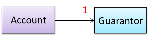
Here, the association is compulsory i.e. an Account object should always be linked to a Guarantor. One way to implement this is to simply use a reference variable, like this:
class Account {
    Guarantor guarantor;

    void setGuarantor(Guarantor g) {
        guarantor = g;
    }
}
However, what if someone else used the Account class like this?
Account a = new Account();
a.setGuarantor(null);
This results in an Account without a Guarantor! In a real banking system, this could have serious consequences! The code here did not try to prevent such a thing from happening. We can make the code more defensive
by proactively enforcing the multiplicity constraint, like this:
class Account {
    private Guarantor guarantor;

    public Account(Guarantor g){
        if (g == null) {
            stopSystemWithMessage("multiplicity violated. Null Guarantor");
        }
        guarantor = g;
    }
    public void setGuarantor (Guarantor g){
        if (g == null) {
            stopSystemWithMessage("multiplicity violated. Null Guarantor");
        }
        guarantor = g;
    }
    …
}
Enforcing 1-to-1 Associations
Consider the association given below. A defensive implementation requires to ensure a MinedCell cannot exist without a Mine and vice versa which requires simultaneous object creation. However, Java can only create one
object at a time. Given below are two alternatives implementations, both of which violate the multiplicity for a short period of time.
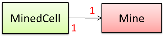
Option 1:
class MinedCell {
    private Mine mine;

    public MinedCell(Mine m){
        if (m == null) {
            showError();
        }
        mine = m;
    }
    …
}
Option 1 forces us to keep a Mine without a MinedCell (until the MinedCell is created).
Option 2:
class MinedCell {
    private Mine mine;

    public MinedCell(){
        mine = new Mine();
    }
    …
}
Option 2 is more defensive because the Mine is immediately linked to a MinedCell.
Enforcing Referential Integrity
A bidirectional association in the design (shown in (a)) is usually emulated at code level using two variables (as shown in (b)).
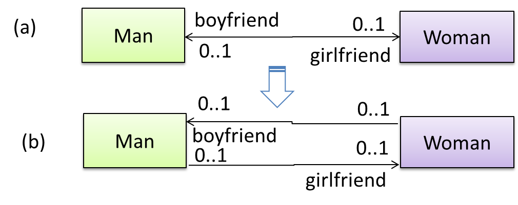
class Man {
    Woman girlfriend;

    void setGirlfriend(Woman w) {
        girlfriend = w;
    }
    …
}
class Woman {
    Man boyfriend;

    void setBoyfriend(Man m) {
        boyfriend = m;
    }
}
The two classes are meant to be used as follows:
Woman jean;
Man james;
…
james.setGirlfriend(jean);
jean.setBoyfriend(james);
Suppose the two classes were used this instead:
Woman jean; Man james, yong;
…
james.setGirlfriend(jean);
jean.setBoyfriend(yong);
Now James' girlfriend is Jean, while Jean's boyfriend is not James. This situation results as the code was not defensive enough to stop this "love triangle". In such a situation, we say that the referential integrity has been violated. It simply means there is an inconsistency in object references.

One way to prevent this situation is to implement the two classes as shown below. Note how the referential integrity is maintained.
public class Woman {
    private Man boyfriend;

    public void setBoyfriend(Man m) {
        if(boyfriend == m){
            return;
        }
        if (boyfriend != null) {
            boyfriend.breakUp();
        }
        boyfriend = m;
        m.setGirlfriend(this);
    }

    public void breakUp() {
        boyfriend = null;
    }
    ...
}
public class Man{
    private Woman girlfriend;

    public void setGirlfriend(Woman w) {
        if(girlfriend == w){
            return;
        }
        if (girlfriend != null) {
            girlfriend.breakUp();
        }
        girlfriend = w;
        w.setBoyfriend(this);
    }
    public void breakUp() {
        girlfriend = null;
    }
   ...
}
When the code james.setGirlfriend(jean) is executed, the code ensures that james break up with any current girlfriend before he accepts jean as the girlfriend. Furthermore, the code ensures that jean breaks up with any existing boyfriends and accepts james as the boyfriend.
When
It is not necessary to be 100% defensive all the time. While defensive code may be less prone to be misused or abused, such code can also be more complicated and slower to run.
The suitable degree of defensiveness depends on many factors such as:
- How critical is the system?
- Will the code be used by programmers other than the author?
- The level of programming language support for defensive programming
- The overhead of being defensive
Design-by-Contract Approach
Design by Contract
Suppose an operation is implemented with the behavior specified precisely in the API (preconditions, post conditions, exceptions etc.). When following the defensive approach, the code should first check if the preconditions have been met. Typically, exceptions are thrown if preconditions are violated. In contrast, the Design-by-Contract (DbC) approach to coding assumes that it is the responsibility of the caller to ensure all preconditions are met. The operation will honor the contract only if the preconditions have been met. If any of them have not been met, the behavior of the operation is "unspecified".
Languages such as Eiffel have native support for DbC. For example, preconditions of an operation can be specified in Eiffel and the language runtime will check precondition violations without the need to do it explicitly in the code. To follow the DbC approach in languages such as Java and C++ where there is no built-in DbC support, assertions can be used to confirm pre-conditions.
Integration
Introduction
What
Combining parts of a software product to form a whole is called integration. It is also one of the most troublesome tasks and it rarely goes smoothly.
Approaches
'Late and One Time' vs 'Early and Frequent'
In terms of timing and frequency, there are two general approaches to integration: late and one-time, early and frequent.
Late and one-time: wait till all components are completed and integrate all finished components near the end of the project.
This approach is not recommended because integration often causes many component incompatibilities (due to previous miscommunications and misunderstandings) to surface which can lead to delivery delays i.e. Late integration → incompatibilities found → major rework required → cannot meet the delivery date.
Early and frequent: integrate early and evolve each part in parallel, in small steps, re-integrating frequently.
📦 A
Here is an animation that compares the two approaches:
Big-Bang vs Incremental Integration
Big-bang integration: integrate all components at the same time.
Big-bang is not recommended because it will uncover too many problems at the same time which could make debugging and bug-fixing more complex than when problems are uncovered incrementally.
Incremental integration: integrate few components at a time. This approach is better than the big-bang integration because it surfaces integration problems in a more manageable way.
Here is an animation that compares the two approaches:
Top-Down vs Bottom-Up Integration
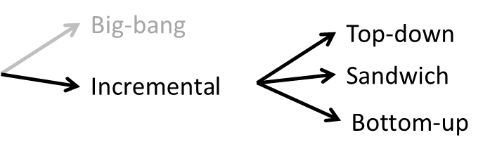
Based on the order in which components are integrated, incremental integration can be done in three ways.
Top-down integration: higher-level components are integrated before bringing in the lower-level components. One advantage of this approach is that higher-level problems can be discovered early. One disadvantage is that
this requires the use of
Stub: A stub has the same interface as the component it replaces, but its implementation is so simple that it is unlikely to have any bugs. It mimics the responses of the component, but only for the a limited set of predetermined inputs. That is, it does not know how to respond to any other inputs. Typically, these mimicked responses are hard-coded in the stub rather than computed or retrieved from elsewhere, e.g. from a database.
Bottom-up integration: the reverse of top-down integration. Note that when integrating lower level components,
Sandwich integration: a mix of the top-down and the bottom-up approaches. The idea is to do both top-down and bottom-up so as to 'meet' in the middle.
Here is an animation that compares the three approaches:
Build Automation
What
Build automation tools automate the steps of the build process, usually by means of build scripts.
In a non-trivial project, building a product from source code can be a complex multi-step process. For example, it can include steps such as to pull code from the revision control system, compile, link, run automated tests, automatically update release documents (e.g. build number), package into a distributable, push to repo, deploy to a server, delete temporary files created during building/testing, email developers of the new build, and so on. Furthermore, this build process can be done ‘on demand’, it can be scheduled (e.g. every day at midnight) or it can be triggered by various events (e.g. triggered by a code push to the revision control system).
Some of these build steps such as to compile, link and package are already automated in most modern IDEs. For example, several steps happen automatically when the ‘build’ button of the IDE is clicked. Some IDEs even allow customization to this build process to some extent.
However, most big projects use specialized build tools to automate complex build processes.
📦 Some popular build tools relevant to Java developers:
📦 Some other build tools : Grunt (JavaScript), Rake (Ruby)
Some build tools also serve as dependency management tools. Modern software projects often depend on third party libraries that evolve constantly. That means developers need to download the correct version of the required libraries and update them regularly. Therefore, dependency management is an important part of build automation. Dependency Management tools can automate that aspect of a project.
📦 Maven and Gradle, in addition to managing the build process, can play the role of dependency management tools too.
Continuous Integration and Continuous Deployment
An extreme application of build automation is called continuous integration (CI) in which integration, building, and testing happens automatically after each code change.
A natural extension of CI is Continuous Deployment (CD) where the changes are not only integrated continuously, but also deployed to end-users at the same time.
📦 Some examples of CI/CD tools:
Reuse
Introduction
What
Reuse is a major theme in software engineering practices. By reusing tried-and-tested components, the robustness of a new software system can be enhanced while reducing the manpower and time requirement. Reusable components come in many forms; it can be reusing a piece of code, a subsystem, or a whole software.
When
While you may be tempted to use many libraries/frameworks/platform that seem to crop up on a regular basis and promise to bring great benefits, note that there are costs associated with reuse. Here are some:
- The reused code may be an overkill (think using a sledgehammer to crack a nut) increasing the size of, or/and degrading the performance of, your software.
- The reused software may not be mature/stable enough to be used in an important product. That means the software can change drastically and rapidly, possibly in ways that break your software.
- Non-mature software has the risk of dying off as fast as they emerged, leaving you with a dependency that is no longer maintained.
- The license of the reused software (or its dependencies) restrict how you can use/develop your software.
- The reused software might have bugs, missing features, or security vulnerabilities that are important to your product but not so important to the maintainers of that software, which means those flaws will not get fixed as fast as you need them to.
- Malicious code can sneak into your product via compromised dependencies.
APIs
What
An Application Programming Interface (API) specifies the interface through which other programs can interact with a software component. It is a contract between the component and its clients.
📦 The API of the Java String class is a collection of public methods that you can invoke to make use of the String class.
📦 The GitHub API is a collection of Web request formats GitHub server accepts and the corresponding responses. We can write a program that interacts with GitHub through that API.
When developing large systems, if you define the API of each components early, the development team can develop the components in parallel because the future behavior of the other components are now more predictable.
Designing APIs
An API should be well-designed (i.e. should cater for the needs of its users) and well-documented.
When we write software consisting of multiple components, we need to define the API of each component.
One approach is to let the API emerge and evolve over time as we write code.
Another approach is to define the API up-front. Doing so allows us to develop the components in parallel.
We can use UML sequence diagrams to analyze the required interactions between components in order to discover the required API. Given below is an example.
Example:
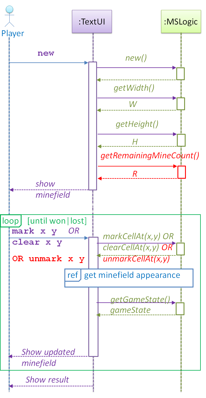
As we analyze the interactions between components using sequence diagrams, we discover the API of those components. For example, the diagram above tells us that the MSLogic component API should have the methods:
new()getWidth:intgetHeight():intgetRemainingMineCount():int
More details can be included to increase the precision of the method definitions before coding. Such precision is important to avoid misunderstandings between the developer of the class and developers of other classes that interact with this class.
- Operation: newGame(): void
- Description: Generates a new WxH minefield with M mines. Any existing minefield will be overwritten.
- Preconditions: None
- Postconditions: A new minefield is created. Game state is READY.
Preconditions are the conditions that must be true before calling this operation. Postconditions describe the system after the operation is complete. Note that post conditions do not say what happens during the operation. Here is another example:
- Operation: clearCellAt(int x, int y): void
- Description: Records the cell at x,y as cleared.
- Parameters: x, y coordinates of the cell
- Preconditions: game state is READY or IN_PLAY. x and y are in 0..(H-1) and 0..(W-1), respectively.
- Postconditions: Cell at x,y changes state to ZERO, ONE, TWO, THREE, …, EIGHT, or INCORRECTLY_CLEARED. Game state changes to IN_PLAY, WON or LOST as appropriate.
Libraries
What
A library is a collection of modular code that is general and can be used by other programs.
📦 Java classes you get with the JDK (such as String, ArrayList, HashMap, etc.) are library classes that are provided in the default Java distribution.
📦 Natty is a Java library that can be used for parsing strings that represent dates e.g. The 31st of April in the year 2008
How
These are the typical steps required to use a library.
- Read the documentation to confirm that its functionality fits your needs
- Check the license to confirm that it allows reuse in the way you plan to reuse it. For example, some libraries might allow non-commercial use only.
- Download the library and make it accessible to your project. Alternatively, you can configure your
dependency management tool to do it for you. - Call the library API from your code where you need to use the library functionality.
Frameworks
What
The overall structure and execution flow of a specific category of software systems can be very similar. The similarity is an opportunity to reuse at a high scale.
📦 Running example:
IDEs for different programming languages are similar in how they support editing code, organizing project files, debugging, etc.
A software framework is a reusable implementation of a software (or part thereof) providing generic functionality that can be selectively customized to produce a specific application.
📦 Running example:
Eclipse is an IDE framework that can be used to create IDEs for different programming languages.
Some frameworks provide a complete implementation of a default behavior which makes them immediately usable.
📦 Running example:
Eclipse is a fully functional Java IDE out-of-the-box.
A framework facilitates the adaptation and customization of some desired functionality.
📦 Running example:
Eclipse plugin system can be used to create an IDE for different programming languages while reusing most of the existing IDE features of Eclipse. E.g. https://marketplace.eclipse.org/content/pydev-python-ide-eclipse
Some frameworks cover only a specific components or an aspect.
📦 JavaFx a framework for creating Java GUIs.
📦 More examples of frameworks
- Drupal: a framework for Web-based applications, content management systems in particular. Implemented using PHP
- Ruby on Rails : another Web-application framework similar to Drupal but uses Ruby instead of PHP
- JUnit: a framework for testing Java code.
Frameworks vs Libraries
Although both frameworks and libraries are reuse mechanisms, there are notable differences:
-
Libraries are meant to be used ‘as is’ while frameworks are meant to be customized/extended. e.g., writing plugins for Eclipse so that it can be used as an IDE for different languages (C++, PHP, etc.), adding modules and themes to Drupal, and adding test cases to JUnit.
-
Your code calls the library code while the framework code calls your code. Frameworks use a technique called inversion of control, aka the “Hollywood principle” (i.e. don’t call us, we’ll call you!). That is, you write code that will be called by the framework, e.g. writing test methods that will be called by the JUnit framework. In the case of libraries, your code calls libraries.
Platforms
What
A platform provides a runtime environment for applications. A platform is often bundled with various libraries, tools, frameworks, and technologies in addition to a runtime environment but the defining characteristic of a software platform is the presence of a runtime environment.
📦 Technically, an operating system can be called a platform. For example, Windows PC is a platform for desktop applications while iOS is a platform for mobile apps.
📦 Two well-known examples of platforms are JavaEE and .NET, both of which sit above Operating systems layer, and are used to develop
- JavaEE (Java Enterprise Edition) is both a framework and a platform for writing enterprise applications. The runtime used by the JavaEE applications is the JVM (Java Virtual Machine) that can run on different Operating Systems.
- .NET is a similar platform and a framework. Its runtime is called CLR (Common Language Runtime) and usually used on Windows machines.
Enterprise Application: ‘enterprise applications’ means software applications used at organizations level and therefore has to meet much higher demands (such as in scalability, security, performance, and robustness) than software meant for individual use.
Cloud Computing
What
Cloud computing is the delivery of computing as a service over the network, rather than a product running on a local machine. This means the actual hardware and software is located at a remote location, typically, at a large server farm, while users access them over the network. Maintenance of the hardware and software is managed by the cloud provider while users typically pay for only the amount of services they use. This model is similar to the consumption of electricity; the power company manages the power plant, while the consumers pay them only for the electricity used. The cloud computing model optimizes hardware and software utilization and reduces the cost to consumers. Furthermore, users can scale up/down their utilization at will without having to upgrade their hardware and software. The traditional non-cloud model of computing is similar to everyone buying their own generators to create electricity for their own use.
Iaas, PaaS, and SaaS

source:https://commons.wikimedia.org
Cloud computing can deliver computing services at three levels:
-
Infrastructure as a service (IaaS) delivers computer infrastructure as a service. For example, a user can deploy virtual servers on the cloud instead of buying physical hardware and installing server software on them. Another example would be a customer using storage space on the cloud for off-site storage of data. Rackspace is an example of an IaaS cloud provider. Amazon Elastic Compute Cloud (Amazon EC2) is another one.
-
Platform as a service (PaaS) provides a platform on which developers can build applications. Developers do not have to worry about infrastructure issues such as deploying servers or load balancing as is required when using IaaS. Those aspects are automatically taken care of by the platform. The price to pay is reduced flexibility; applications written on PaaS are limited to facilities provided by the platform. A PaaS example is the Google App Engine where developers can build applications using Java, Python, PHP, or Go whereas Amazon EC2 allows users to deploy application written in any language on their virtual servers.
-
Software as a service (SaaS) allows applications to be accessed over the network instead of installing them on a local machine. For example, Google Docs is an SaaS word processing software, while Microsoft Word is a traditional word processing software.
SECTION: QUALITY ASSURANCE
Quality Assurance
Introduction
What
Software Quality Assurance (QA) is the process of ensuring that the software being built has the required levels of quality.
While testing is the most common activity used in QA, there are other complementary techniques such as static analysis, code reviews, and formal verification.
Validation vs Verification
Quality Assurance = Validation + Verification
QA involves checking two aspects:
- Validation: are we building the right system i.e., are the requirements correct?
- Verification: are we building the system right i.e., are the requirements implemented correctly?
Whether something belongs under validation or verification is not that important. What is more important is both are done, instead of limiting to verification (i.e., remember that the requirements can be wrong too).
Code Reviews
What
Code review is the systematic examination code with the intention of finding where the code can be improved.
Reviews can be done in various forms. Some examples below:
-
In
pair programming - As pair programming involves two programmers working on the same code at the same time, there is an implicit review of the code by the other member of the pair.
Pair Programming:
Pair programming is an agile software development technique in which two programmers work together at one workstation. One, the driver, writes code while the other, the observer or navigator, reviews each line of code as it is typed in. The two programmers switch roles frequently. [source: Wikipedia]

📺 A good introduction to pair programming:
-
Pull Request reviews
- Project Management Platforms such as GitHub and BitBucket allows the new code to be proposed as Pull Requests and provides the ability for others to review the code in the PR.
-
Formal inspections
-
Inspections involve a group of people systematically examining a project artifacts to discover defects. Members of the inspection team play various roles during the process, such as:
- the author - the creator of the artifact
- the moderator - the planner and executor of the inspection meeting
- the secretary - the recorder of the findings of the inspection
- the inspector/reviewer - the one who inspects/reviews the artifact.
-
Advantages of code reviews over testing:
- It can detect functionality defects as well as other problems such as coding standard violations.
- Can verify non-code artifacts and incomplete code
- Do not require test drivers or stubs.
Disadvantages:
- It is a manual process and therefore, error prone.
Static Analysis
What
Static analysis: Static analysis is the analysis of code without actually executing the code.
Static analysis of code can find useful information such unused variables, unhandled exceptions, style errors, and statistics. Most modern IDEs come with some inbuilt static analysis capabilities. For example, an IDE can highlight unused variables as you type the code into the editor.
Higher-end static analyzer tools can perform for more complex analysis such as locating potential bugs, memory leaks, inefficient code structures etc.
📦 Some example static analyzer for Java:
Linters are a subset of static analyzers that specifically aim to locate areas where the code can be made 'cleaner'.
Formal Verification
What
Formal verification uses mathematical techniques to prove the correctness of a program.
📺 An introduction to Formal Methods by Eric Hehner
Advantages:
- Formal verification can be used to prove the absence of errors. In contrast, testing can only prove the presence of error, not their absence.
Disadvantages:
- It only proves the compliance with the specification, but not the actual utility of the software.
- It requires highly specialized notations and knowledge which makes it an expensive technique to administer. Therefore, formal verifications are more commonly used in safety-critical software such as flight control systems.
Testing
Introduction
Testing: Testing is operating a system or component under specified conditions, observing or recording the results, and making an evaluation of some aspect of the system or component. –- source: IEEE
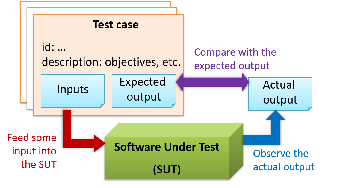
When testing, we execute a set of test cases. A test case specifies how to perform a test. At a minimum, it specifies the input to the software under test (SUT) and the expected behavior.
📦 Example: A minimal test case for testing a browser:
- Input – Start the browser using a blank page (vertical scrollbar disabled). Then, load
longfile.htmllocated in thetest datafolder. - Expected behavior – The scrollbar should be automatically enabled upon loading
longfile.html.
Test cases can be determined based on the specification, reviewing similar existing systems, or comparing to the past behavior of the SUT.
A more elaborate test case can have other details such as those given below.
- A unique identifier : e.g. TC0034-a
- A descriptive name: e.g. vertical scrollbar activation for long web pages
- Objectives: e.g. to check whether the vertical scrollbar is correctly activated when a long web page is loaded to the browser
- Classification information: e.g. priority - medium, category - UI features
- Cleanup, if any: e.g. empty the browser cache.
For each test case we do the following:
- Feed the input to the SUT
- Observe the actual output
- Compare actual output with the expected output
A test case failure is a mismatch between the expected behavior and the actual behavior. A failure is caused by a defect (or a bug).
📦 Example: In the browser example above, a test case failure is implied if the scrollbar remains disabled after loading ‘longfile.html’. The defect/bug causing that failure could be an uninitialized variable.
Here is another definition of testing:
Software testing consists of the dynamic verification that a program provides expected behaviors on a finite set of test cases, suitably selected from the usually infinite execution domain. -– source: Software Engineering Book of Knowledge V3
Some things to note (indicated by keywords in the above definition):
- Dynamic: Testing involves executing the software. It is not by examining the code statically.
- Finite: In most non-trivial cases there are potentially infinite test scenarios but resource constraints dictate that we can test only a finite number of scenarios.
- Selected: In most cases it is not possible to test all scenarios. That means we need to select what scenarios to test.
- Expected: Testing requires some knowledge of how the software is expected to behave.
Testability
Testability is an indication of how easy it is to test an SUT. As testability depends a lot on the design and implementation. You should try to increase the testability when you design and implement a software. The higher the testability, the easier it is to achieve a better quality software.
Testing Types
Unit Testing
What
Unit testing : testing individual units (methods, classes, subsystems, ...) to ensure each piece works correctly.
In OOP code, it is common to write one or more unit tests for each public method of a class.
📦 Here are the code skeletons for a Foo class containing two methods and a FooTest class that contains JUnit tests for those two methods.
class Foo{
    String read(){
        //...
    }

    void write(String input){
        //...
    }

}

class FooTest{

    @Test
    void read(){
        //a unit test for Foo#read() method
    }

    @Test
    void write_emptyInput_exceptionThrown(){
        //a unit tests for Foo#write(String) method
    }

    @Test
    void write_normalInput_writtenCorrectly(){
        //another unit tests for Foo#write(String) method
    }
}
Stubs
A proper unit test requires the unit to be tested in isolation so that bugs in the
📦 If a Logic class depends on a Storage class, unit testing the Logic class requires isolating the Logic class from the Storage class.
Stubs can isolate the
Stub: A stub has the same interface as the component it replaces, but its implementation is so simple that it is unlikely to have any bugs. It mimics the responses of the component, but only for the a limited set of predetermined inputs. That is, it does not know how to respond to any other inputs. Typically, these mimicked responses are hard-coded in the stub rather than computed or retrieved from elsewhere, e.g. from a database.
📦 Consider the code below:
class Logic {
    Storage s;

    Logic(Storage s) {
        this.s = s;
    }

    String getName(int index) {
        return "Name: " + s.getName(index);
    }
}

interface Storage {
    String getName(int index);
}

class DatabaseStorage implements Storage {

    @Override
    public String getName(int index) {
        return readValueFromDatabase(index);
    }

    private String readValueFromDatabase(int index) {
        // retrieve name from the database
    }
}
Normally, you would use the Logic class as follows (not how the Logic object depends on a DatabaseStorage object to perform the getName() operation):
Logic logic = new Logic(new DatabaseStorage());
String name = logic.getName(23);
You can test it like this:
@Test
void getName() {
    Logic logic = new Logic(new DatabaseStorage());
    assertEquals("Name: John", logic.getName(5));
}
However, this logic object being tested is making use of a DataBaseStorage object which means a bug in the DatabaseStorage class can affect the test. Therefore, this test is not testing Logic in isolation from its dependencies and hence it is not a pure unit test.
Here is a stub class you can use in place of DatabaseStorage:
class StorageStub implements Storage {

    @Override
    public String getName(int index) {
        if(index == 5) {
            return "Adam";
        } else {
            throw new UnsupportedOperationException();
        }
    }
}
Note how the stub has the same interface as the real dependency, is so simple that it is unlikely to contain bugs, and is pre-configured to respond with a hard-coded response, presumably, the correct response DatabaseStorage is
expected to return for the given test input.
Here is how you can use the stub to write a unit test. This test is not affected by any bugs in the DatabaseStorage class and hence is a pure unit test.
@Test
void getName() {
    Logic logic = new Logic(new StorageStub());
    assertEquals("Name: Adam", logic.getName(5));
}
In addition to Stubs, there are other type of replacements you can use during testing. E.g. Mocks, Fakes, Dummies, Spies.
Integration Testing
What
Integration testing : testing whether different parts of the software work together (i.e. integrates) as expected. Integration tests aim to discover bugs in the 'glue code' related to how components interact with each other. These bugs are often the result of misunderstanding of what the parts are supposed to do vs what the parts are actually doing.
📦 Suppose a class Car users classes Engine and Wheel. If the Car class assumed a Wheel can support 200 mph speed but the Wheel can only support 150 mph, it is the
integration test that is supposed to uncover this discrepancy.
System Testing
What
System testing: take the whole system and test it against the system specification.
System testing is typically done by a testing team (also called a QA team).
System test cases are based on the specified external behavior of the system. Sometimes, system tests go beyond the bounds defined in the specification. This is useful when testing that the system fails 'gracefully' having pushed beyond its limits.
📦 Suppose the SUT is a browser capable of handling web pages containing up to 5000 characters. Given below is a test case to test if the SUT fails gracefully if pushed beyond its limits.
Test case: load a web page that is too big
* Input: load a web page containing more than 5000 characters.
* Expected behavior: abort the loading of the page and show a meaningful error message.
This test case would fail if the browser attempted to load the large file anyway and crashed.
System testing includes testing against non-functional requirements too. Here are some examples.
- Performance testing – to ensure the system responds quickly.
- Load testing (also called stress testing or scalability testing) – to ensure the system can work under heavy load.
- Security testing – to test how secure the system is.
- Compatibility testing, interoperability testing – to check whether the system can work with other systems.
- Usability testing – to test how easy it is to use the system.
- Portability testing – to test whether the system works on different platforms.
Alpha-Beta Testing
What
Alpha testing is performed by the users, under controlled conditions set by the software development team.
Beta testing is performed by a selected subset of target users of the system in their natural work setting.
An open beta release is the release of not-yet-production-quality-but-almost-there software to the general population. For example, Google’s Gmail was in 'beta' for many years before the label was finally removed.
Dogfooding
What
Eating your own dog food (aka dogfooding), is a creators of a product use their own product to test the product.
Developer Testing
What
Developer testing is the testing done by the developers themselves as opposed to professional testers or end-users.
Why
Delaying testing until the full product is complete has a number of disadvantages:
- Locating the cause of such a test case failure is difficult due to a large search space; in a large system, the search space could be millions of lines of code, written by hundreds of developers! The failure may also be due to multiple inter-related bugs.
- Fixing a bug found during such testing could result in major rework, especially if the bug originated during the design or during requirements specification (i.e. a faulty design or faulty requirements).
- One bug might 'hide' other bugs, which could emerge only after the first bug is fixed.
- The delivery may have to be delayed if too many bugs were found during testing.
Therefore, it is better to do early testing, as hinted by the popular rule of thumb given below, also illustrated by the graph below it.
The earlier a bug is found, the easier and cheaper to have it fixed.
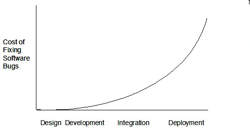
Such early testing of partially developed software is usually, and by necessity, done by the developers themselves i.e. developer testing.
Exploratory vs Scripted Testing
What
Here are two alternative approaches to testing a software: Scripted testing and Exploratory testing
-
Scripted testing: First write a set of test cases based on the expected behavior of the SUT, and then perform testing based on that set of test cases.
-
Exploratory testing: Devise test cases on-the-fly, creating new test cases based on the results of the past test cases.
Exploratory testing is ‘the simultaneous learning, test design, and test execution’
📦 Here is an example thought process behind a segment of an exploratory testing session:
“Hmm... looks like feature x is broken. This usually means feature n and k could be broken too; we need to look at them soon. But before that, let us give a good test run to feature y because users can still use the product if feature y works, even if x doesn’t work. Now, if feature y doesn’t work 100%, we have a major problem and this has to be made known to the development team sooner rather than later...”
Exploratory testing is also known as reactive testing, error guessing technique, attack-based testing, and bug hunting.
Exploratory Testing Explained, an online article by James Bach -- James Bach is an industry thought leader in software testing).
When
Which approach is better – scripted or exploratory? A mix is better.
The success of exploratory testing depends on the tester’s prior experience and intuition. Exploratory testing should be done by experienced testers, using a clear strategy/plan/framework. Ad-hoc exploratory testing by unskilled or inexperienced testers without a clear strategy is not recommended for real-world non-trivial systems. While exploratory testing may allow us to detect some problems in a relatively short time, it is not prudent to use exploratory testing as the sole means of testing a critical system.
Scripted testing is more systematic, and hence, likely to discover more bugs given sufficient time, while exploratory testing would aid in quick error discovery, especially if the tester has a lot of experience in testing similar systems.
In some contexts, you will achieve your testing mission better through a more scripted approach; in other contexts, your mission will benefit more from the ability to create and improve tests as you execute them. I find that most situations benefit from a mix of scripted and exploratory approaches. --
[source: bach-et-explained]
Exploratory Testing Explained, an online article by James Bach -- James Bach is an industry thought leader in software testing).
Acceptance Testing
What
Acceptance testing (aka User Acceptance Testing (UAT)): test the delivered system to ensure it meets the user requirements.
Acceptance tests give an assurance to the customer that the system does what it is intended to do. Acceptance test cases are often defined at the beginning of the project, usually based on the use case specification. Successful completion of UAT is often a prerequisite to the project sign-off.
Acceptance vs System Testing
Acceptance testing comes after system testing. Similar to system testing, acceptance testing involves testing the whole system.
Some differences between system testing and acceptance testing:
| System Testing | Acceptance Testing |
|---|---|
| Done against the system specification | Done against the requirements specification |
| Done by testers of the project team | Done by a team that represents the customer |
| Done on the development environment or a test bed | Done on the deployment site or on a close simulation of the deployment site |
| Both negative and positive test cases | More focus on positive test cases |
Note: negative test cases: cases where the SUT is not expected to work normally e.g. incorrect inputs; positive test cases: cases where the SUT is expected to work normally
Requirement Specification vs System Specification
The requirement specification need not be the same as the system specification. Some example differences:
| Requirements Specification | System Specification |
|---|---|
| limited to how the system behaves in normal working conditions | can also include details on how it will fail gracefully when pushed beyond limits, how to recover, etc. specification |
| written in terms of problems that need to be solved (e.g. provide a method to locate an email quickly) | written in terms of how the system solve those problems (e.g. explain the email search feature) |
| specifies the interface available for intended end-users | could contain additional APIs not available for end-users (for the use of developers/testers) |
However, in many cases one document serves as both a requirement specification and a system specification.
Passing system tests does not necessarily mean passing acceptance testing. Some examples:
- The system might work on the testbed environments but might not work the same way in the deployment environment, due to subtle differences between the two environments.
- The system might conform to the system specification but could fail to solve the problem it was supposed to solve for the user, due to flaws in the system design.
Regression Testing
When we modify a system, the modification may result in some unintended and undesirable effects on the system. Such an effect is called a regression.
Regression testing is re-testing the
Regression testing is more effective when it is done frequently, after each small change. However, doing so can be prohibitively expensive if testing is done manually. Hence, regression testing is more practical when it is automated.
Stub: A stub has the same interface as the component it replaces, but its implementation is so simple that it is unlikely to have any bugs. It mimics the responses of the component, but only for the a limited set of predetermined inputs. That is, it does not know how to respond to any other inputs. Typically, these mimicked responses are hard-coded in the stub rather than computed or retrieved from elsewhere, e.g. from a database.
SUT: Software Under Test
T
Testing: Testing is operating a system or component under specified conditions, observing or recording the results, and making an evaluation of some aspect of the system or component. –- source: IEEE
Type Signature: The type signature of an operation is the type sequence of the parameters. The return type and parameter names are not part of the type signature. However, the parameter order is significant.
| Method | Type Signature |
|---|---|
int add(int X, int Y) |
(int, int) |
void add(int A, int B) |
(int, int) |
void m(int X, double Y) |
(int, double) |
void m(double X, int Y) |
(double, int) |
U
Unified Modeling Language (UML) is a graphical notation to describe various aspects of a software system. UML is the brainchild of three software modeling specialists James Rumbaugh, Grady Booch and Ivar Jacobson (also known as the Three Amigos). Each of them has developed their own notation for modeling software systems before joining force to create a unified modeling language (hence, the term ‘Unified’ in UML). UML is currently the de facto modeling notation used in the software industry.
Use Case: A description of a set of sequences of actions, including variants, that a system performs to yield an observable result of value to an
Actor: An actor (in a use case) is a role played by a user. An actor can be a human or another system. Actors are not part of the system; they reside outside the system.
User story: User stories are short, simple descriptions of a feature told from the perspective of the person who desires the new capability, usually a user or customer of the system. [Mike Cohn]
User story format: As a {user type/role} I can {function} so that {benefit}
W
Working directory: The directory the repo is based in is called the working directory.
Y
YAGNI (You Aren't Gonna Need It!) Principle: Do not add code simply because ‘you might need it in the future’.
Test Automation
An automated test case can be run programmatically and the result of the test case (pass or fail) is determined programmatically. Compared to manual testing, automated testing reduces the effort required to run tests repeatedly and increases precision of testing (because manual testing is susceptible to human errors).
A simple way to semi-automate testing of a
- First, we feed the app with a sequence of test inputs that is stored in a file while redirecting the output to another file.
e.g.,java AddressBook < input.txt > output.txt - Next, we compare the actual output file with another file containing the expected output.
e.g.,FC output.txt expected.txt
Let us assume we are testing a CLI app called AddressBook (Example: se-edu/addressbook-level1). Here are the detailed steps:
-
Store the test input in the text file
input.txt.add Valid Name p/12345 valid@email.butNoPrefix add Valid Name 12345 e/valid@email.butPhonePrefixMissing -
Store the output we expect from the SUT in another text file
expected.txt.Command: || [add Valid Name p/12345 valid@email.butNoPrefix] Invalid command format: add Command: || [add Valid Name 12345 e/valid@email.butPhonePrefixMissing] Invalid command format: add -
Run the program as given below, which will redirect the text in
input.txtas the input toAddressBookand similarly, will redirect the output of AddressBook to a text fileoutput.txt. Note that this does not require any code changes toAddressBook.java AddressBook < input.txt > output.txtA CLI program takes input from the keyboard and outputs to the console. That is because those two are default input and output streams, respectively. But you can change that behavior using
<and>operators. For example, if you runAddressBookin the DOS prompt, the output will be shown in the console, but if you run it like this,java AddressBook > output.txtthe Operating System then creates a file
output.txtand stores the output in that file instead of displaying it in the console. No file I/O coding is required. Similarly, adding< input.txt(or any other filename) makes the OS redirect the contents of the file as input to the program, as if the user typed the content of the file one line at a time.📎 Resources:
-
Next, we compare
output.txtwith theexpected.txt. This can be done using a utility such as WindowsFC(i.e. File Compare) command, Unixdiffcommand, or a GUI tool such as Winmerge.FC output.txt expected.txt
Note that the above technique is only suitable when testing CLI apps, and only if the exact output can be predetermined. If the output varies from one run to the other (e.g. it contains a time stamp), this technique will not work. In those cases we need more sophisticated ways of automating tests.
CLI App: An application that has a Command Line Interface. i.e. user interacts with the app by typing in commands.
Test Automation Using Test Drivers
A test driver is the code that ‘drives’ the
📦 PayrollTest ‘drives’ the PayRoll class by sending it test inputs and verifies if the output is as expected.
public class PayrollTestDriver {
    public static void main(String[] args) throws Exception {

        //test setup
        Payroll p = new Payroll();

        //test case 1
        p.setEmployees(new String[]{"E001", "E002"});
        // automatically verify the response
        if (p.totalSalary() != 6400) {
            throw new Error("case 1 failed ");
        }

        //test case 2
        p.setEmployees(new String[]{"E001"});
        if (p.totalSalary() != 2300) {
            throw new Error("case 2 failed ");
        }

        //more tests...

        System.out.println("All tests passed");
    }
}
Test Automation Tools
JUnit is a tool for automated testing of Java programs. Similar tools are available for other languages.
📦 This an automated test for a Payroll class, written using JUnit libraries.
public class PayrollTestJUnit {

    @Test
    public void testTotalSalary(){
        Payroll p = new Payroll();

        //test case 1
        p.setEmployees(new String[]{"E001", "E002"});
        assertEquals(p.totalSalary(), 6400);

        //test case 2
        p.setEmployees(new String[]{"E001"});
        assertEquals(p.totalSalary(), 2300);

        //more tests...
    }
}
Most modern IDEs has integrated support for testing tools. The figure below shows the JUnit output when running some JUnit tests using the Eclipse IDE.
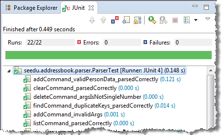
Automated Testing of GUIs
If a software product has a GUI component, all product-level testing (i.e. the types of testing mentioned above) need to be done using the GUI. However, testing the GUI is much harder than testing the CLI (command line interface) or API, for the following reasons:
- Most GUIs can support a large number of different operations, many of which can be performed in any arbitrary order.
- GUI operations are more difficult to automate than API testing. Reliably automating GUI operations and automatically verifying whether the GUI behaves as expected is harder than calling an operation and comparing its return value with an expected value. Therefore, automated regression testing of GUIs is rather difficult.
- The appearance of a GUI (and sometimes even behavior) can be different across platforms and even environments. For example, a GUI can behave differently based on whether it is minimized or maximized, in focus or out of focus, and in a high resolution display or a low resolution display.
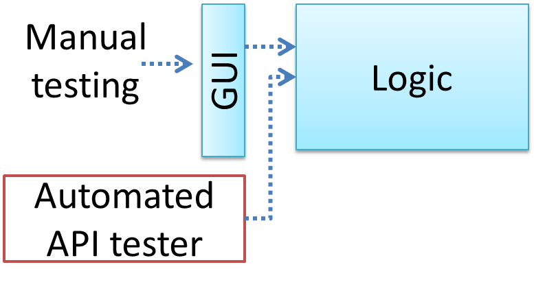
One approach to overcome the challenges of testing GUIs is to minimize logic aspects in the GUI. Then, bypass the GUI to test the rest of the system using automated API testing. While this still requires the GUI to be tested manually, the number of such manual test cases can be reduced as most of the system has been tested using automated API testing.
There are testing tools that can automate GUI testing.
📦 Some tools used for automated GUI testing:
Test Coverage
What
Test coverage is a metric used to measure the extent to which testing exercises the code i.e., how much of the code is 'covered' by the tests.
Here are some examples of different coverage criteria:
- Function/method coverage : based on functions executed e.g., testing executed 90 out of 100 functions.
- Statement coverage : based on the number of line of code executed e.g., testing executed 23k out of 25k LOC.
- Decision/branch coverage : based on the decision points exercised e.g., an
ifstatement evaluated to bothtrueandfalsewith separate test cases during testing is considered 'covered'. - Condition coverage : based on the boolean sub-expressions, each evaluated to both true and false with different test cases. Condition coverage is not the same as the decision coverage.
📦 if(x > 2 && x < 44) is considered one decision point but two conditions.
For 100% branch or decision coverage, two test cases are required:
(x > 2 && x < 44) == true: [e.g.x == 4](x > 2 && x < 44) == false: [e.g.x == 100]
For 100% condition coverage, three test cases are required
(x > 2) == true,(x < 44) == true: [e.g.x == 4](x < 44) == false: [e.g.x == 100](x > 2) == false: [e.g.x == 0]
- Path coverage measures coverage in terms of possible paths through a given part of the code executed. 100% path coverage means all possible paths have been executed. A commonly used notation for path analysis is called the Control Flow Graph (CFG).
- Entry/exit coverage measures coverage in terms of possible calls to and exits from the operations in the SUT.
How
Measuring coverage is often done using coverage analysis tools. Most IDEs have inbuilt support for measuring test coverage, or at least have plugins that can measure test coverage.
Coverage analysis can be useful in improving the quality of testing e.g., if a set of test cases does not achieve 100% branch coverage, more test cases can be added to cover missed branches.
📺 Measuring code coverage in Intellij IDEA
Dependency Injection
What
Dependency injection is the process of 'injecting' objects to replace current dependencies with a different object. This is often used to inject
Quality Assurance → Testing → Unit Testing →
Stubs
A proper unit test requires the unit to be tested in isolation so that bugs in the
📦 If a Logic class depends on a Storage class, unit testing the Logic class requires isolating the Logic class from the Storage class.
Stubs can isolate the
Stub: A stub has the same interface as the component it replaces, but its implementation is so simple that it is unlikely to have any bugs. It mimics the responses of the component, but only for the a limited set of predetermined inputs. That is, it does not know how to respond to any other inputs. Typically, these mimicked responses are hard-coded in the stub rather than computed or retrieved from elsewhere, e.g. from a database.
📦 Consider the code below:
class Logic {
    Storage s;

    Logic(Storage s) {
        this.s = s;
    }

    String getName(int index) {
        return "Name: " + s.getName(index);
    }
}

interface Storage {
    String getName(int index);
}

class DatabaseStorage implements Storage {

    @Override
    public String getName(int index) {
        return readValueFromDatabase(index);
    }

    private String readValueFromDatabase(int index) {
        // retrieve name from the database
    }
}
Normally, you would use the Logic class as follows (not how the Logic object depends on a DatabaseStorage object to perform the getName() operation):
Logic logic = new Logic(new DatabaseStorage());
String name = logic.getName(23);
You can test it like this:
@Test
void getName() {
    Logic logic = new Logic(new DatabaseStorage());
    assertEquals("Name: John", logic.getName(5));
}
However, this logic object being tested is making use of a DataBaseStorage object which means a bug in the DatabaseStorage class can affect the test. Therefore, this test is not testing Logic in isolation from its dependencies and hence it is not a pure unit test.
Here is a stub class you can use in place of DatabaseStorage:
class StorageStub implements Storage {

    @Override
    public String getName(int index) {
        if(index == 5) {
            return "Adam";
        } else {
            throw new UnsupportedOperationException();
        }
    }
}
Note how the stub has the same interface as the real dependency, is so simple that it is unlikely to contain bugs, and is pre-configured to respond with a hard-coded response, presumably, the correct response DatabaseStorage is expected to return for the given test input.
Here is how you can use the stub to write a unit test. This test is not affected by any bugs in the DatabaseStorage class and hence is a pure unit test.
@Test
void getName() {
    Logic logic = new Logic(new StorageStub());
    assertEquals("Name: Adam", logic.getName(5));
}
In addition to Stubs, there are other type of replacements you can use during testing. E.g. Mocks, Fakes, Dummies, Spies.
- Mocks Aren't Stubs by Martin Fowler -- An in-depth article about how Stubs differ from other types of test helpers.
Stubs help us to test a component in isolation from its dependencies.
True
📦 A Foo object normally depends on a Bar object, but we can inject a BarStub object so that the Foo object no longer depends on a Bar object. Now we can test the Foo object in isolation from the Bar object.
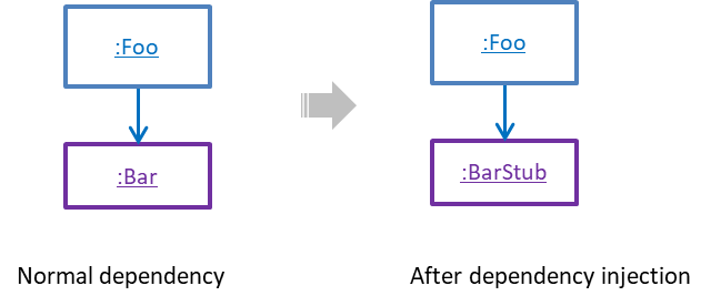
How
Polymorphism can be used to implement dependency injection, as can be seen in the example given in
Quality Assurance → Testing → Unit Testing →
Stubs
A proper unit test requires the unit to be tested in isolation so that bugs in the
📦 If a Logic class depends on a Storage class, unit testing the Logic class requires isolating the Logic class from the Storage class.
Stubs can isolate the
Stub: A stub has the same interface as the component it replaces, but its implementation is so simple that it is unlikely to have any bugs. It mimics the responses of the component, but only for the a limited set of predetermined inputs. That is, it does not know how to respond to any other inputs. Typically, these mimicked responses are hard-coded in the stub rather than computed or retrieved from elsewhere, e.g. from a database.
📦 Consider the code below:
class Logic {
    Storage s;

    Logic(Storage s) {
        this.s = s;
    }

    String getName(int index) {
        return "Name: " + s.getName(index);
    }
}

interface Storage {
    String getName(int index);
}

class DatabaseStorage implements Storage {

    @Override
    public String getName(int index) {
        return readValueFromDatabase(index);
    }

    private String readValueFromDatabase(int index) {
        // retrieve name from the database
    }
}
Normally, you would use the Logic class as follows (not how the Logic object depends on a DatabaseStorage object to perform the getName() operation):
Logic logic = new Logic(new DatabaseStorage());
String name = logic.getName(23);
You can test it like this:
@Test
void getName() {
    Logic logic = new Logic(new DatabaseStorage());
    assertEquals("Name: John", logic.getName(5));
}
However, this logic object being tested is making use of a DataBaseStorage object which means a bug in the DatabaseStorage class can affect the test. Therefore, this test is not testing Logic in isolation from its dependencies and hence it is not a pure unit test.
Here is a stub class you can use in place of DatabaseStorage:
class StorageStub implements Storage {

    @Override
    public String getName(int index) {
        if(index == 5) {
            return "Adam";
        } else {
            throw new UnsupportedOperationException();
        }
    }
}
Note how the stub has the same interface as the real dependency, is so simple that it is unlikely to contain bugs, and is pre-configured to respond with a hard-coded response, presumably, the correct response DatabaseStorage is expected to return for the given test input.
Here is how you can use the stub to write a unit test. This test is not affected by any bugs in the DatabaseStorage class and hence is a pure unit test.
@Test
void getName() {
    Logic logic = new Logic(new StorageStub());
    assertEquals("Name: Adam", logic.getName(5));
}
In addition to Stubs, there are other type of replacements you can use during testing. E.g. Mocks, Fakes, Dummies, Spies.
- Mocks Aren't Stubs by Martin Fowler -- An in-depth article about how Stubs differ from other types of test helpers.
Stubs help us to test a component in isolation from its dependencies.
True
📦 Here is another example of using polymorphism to implement dependency injection:
Suppose we want to unit test the Payroll#totalSalary() given below. The method depends on the SalaryManager object to calculate the return value. Note how the setSalaryManager(SalaryManager) can be used
to inject a SalaryManager object to replace the current SalaryManager object.
class Payroll {
    private SalaryManager manager = new SalaryManager();
    private String[] employees;

    void setEmployees(String[] employees) {
        this.employees = employees;
    }

    void setSalaryManager(SalaryManager sm) {
       this. manager = sm;
    }

    double totalSalary() {
        double total = 0;
        for(int i = 0;i < employees.length; i++){
            total += manager.getSalaryForEmployee(employees[i]);
        }
        return total;
    }
}


class SalaryManager {
    double getSalaryForEmployee(String empID){
        //code to access employee’s salary history
        //code to calculate total salary paid and return it
    }
}
During testing, you can inject a SalaryManagerStub object to replace the SalaryManager object.
class PayrollTest {
    public static void main(String[] args) {
        //test setup
        Payroll p = new Payroll();
        p.setSalaryManager(new SalaryManagerStub()); //dependency injection
        //test case 1
        p.setEmployees(new String[]{"E001", "E002"});
        assertEquals(2500.0, p.totalSalary());
        //test case 2
        p.setEmployees(new String[]{"E001"});
        assertEquals(1000.0, p.totalSalary());
        //more tests ...
    }
}


class SalaryManagerStub extends SalaryManager {
    /** Returns hard coded values used for testing */
    double getSalaryForEmployee(String empID) {
        if(empID.equals("E001")) {
            return 1000.0;
        } else if(empID.equals("E002")) {
            return 1500.0;
        } else {
            throw new Error("unknown id");
        }
    }
}
TDD
What
Test-Driven Development(TDD)_ advocates writing the tests before writing the SUT, while evolving functionality and tests in small increments. In TDD you first define the precise behavior of the SUT using test cases, and then write the SUT to match the specified behavior. While TDD has its fair share of detractors, there are many who consider it a good way to reduce defects. One big advantage of TDD is that it guarantees the code is testable.
How
Note that TDD does not imply writing all the test cases first before writing functional code. Rather, proceed in small steps:
- Decide what behavior to implement.
- Write test cases to test that behavior.
- Run those test cases and watch them fail.
- Implement the behavior.
- Run the test case.
- Keep modifying the code and rerunning test cases until they all pass.
- Refactor code to improve quality.
- Repeat the cycle for each small unit of behavior that needs to be implemented.
Test Case Design
Introduction
What
Except for trivial
📦 Consider the test cases for adding a String object to a Collection object:
- Add an item to an empty collection.
- Add an item when there is one item in the collection.
- Add an item when there are 2, 3, .... n items in the collection.
- Add an item that has an English, a French, a Spanish, ... word.
- Add an item that is the same as an existing item.
- Add an item immediately after adding another item.
- Add an item immediately after system startup.
- ...
Exhaustive testing of this operation can take many more test cases.
Program testing can be used to show the presence of bugs, but never to show their absence!
--Edsger Dijkstra
Every test case adds to the cost of testing. In some systems, a single test case can cost thousands of dollars e.g. on-field testing of flight-control software. Therefore, test cases need to be designed to make the best use of testing resources. In particular:
-
Testing should be effective i.e., it finds a high % of existing bugs e.g., a set of test cases that finds 60 defects is more effective than a set that finds only 30 defects in the same system.
-
Testing should be efficient i.e., it has a high rate of success (bugs found/test cases) a set of 20 test cases that finds 8 defects is more efficient than another set of 40 test cases that finds the same 8 defects.
For testing to be
Positive vs Negative Test Cases
A positive test case is when the test is designed to produce an expected/valid behavior. A negative test case is designed to produce a behavior that indicates an invalid/unexpected situation, such as an error message.
📦 Consider testing of the method print(Integer i) which prints the value of i.
- A positive test case:
i == new Integer(50) - A negative test case:
i == null;
Black Box vs Glass Box
Test case design can be of three types, based on how much of SUT internal details are considered when designing test cases:
-
Black-box (aka specification-based or responsibility-based) approach: test cases are designed exclusively based on the SUT’s specified external behavior.
-
White-box (aka glass-box or structured or implementation-based) approach: test cases are designed based on what is known about the SUT’s implementation, i.e. the code.
-
Gray-box approach: test case design uses some important information about the implementation. For example, if the implementation of a sort operation uses different algorithms to sort lists shorter than 1000 items and lists longer than 1000 items, more meaningful test cases can then be added to verify the correctness of both algorithms.
Note: these videos are from the Udacity course Software Development Process by Georgia Tech
Equivalence Partitions
What
Consider the testing of the following operation.
isValidMonth (int m): boolean : returns true if m is in the range [1..12]
It is inefficient and impractical to test this method for all integer values [-MIN_INT to MAX_INT]. Fortunately, there is no need to test all possible input values. For example, if the input value 233 failed to produce
the correct result, the input 234 is likely to fail too; there is no need to test both.
In general, most SUTs do not treat each input in a unique way. Instead, they process all possible inputs in a small number of distinct ways. That means a range of inputs is treated the same way inside the SUT. Equivalence partitioning (EP) is a test case design technique that uses the above observation to improve the E&E of testing.
Equivalence partition (aka equivalence class): A group of test inputs that are likely to be processed by the SUT in the same way.
By dividing possible inputs into equivalence partitions we can,
- avoid testing too many inputs from one partition. Testing too many inputs from the same partition is unlikely to find new bugs. This increases the efficiency of testing by reducing redundant test cases.
- ensure all partitions are tested. Missing partitions can result in bugs going unnoticed. This increases the effectiveness of testing by increasing the chance of finding bugs.
Basic
Equivalence partitions (EPs) are usually derived from the specifications of the SUT.
📦 These could be EPs for the
- [MIN_INT ... 0] : below the range that produces
true - [1 … 12] : the range that produces
true - [13 … MAX_INT] : above the range that produces
true
isValidMonth (int m): boolean : returns true if m is in the range [1..12]
When the SUT has multiple inputs, you should identify EPs for each input.
📦 Consider the method duplicate(String s, int n): String which returns a String that contains s repeated n times.
Example EPs for s:
- zero-length strings
- string containing whitespaces
- ...
Example EPs for n:
0- negative values
- ...
An EP may not have adjacent values.
📦 Consider the method isPrime(int i):boolean that returns true if i is a prime number.
EPs for i:
- prime numbers
- non-prime numbers
Some inputs have only a small number of possible values and a potentially unique behavior for each value. In those cases we have to consider each value as a partition by itself.
📦 Consider the method showStatusMessage(GameStatus s):String that returns a unique String for each of the possible value of s (GameStatus is an enum). In this case, each possible value for
s will have to be considered as a partition.
Note that the EP technique is merely a heuristic and not an exact science, especially when applied manually (as opposed to using an automated program analysis tool to derive EPs). The partitions derived depend on how one ‘speculates’ the SUT to behave internally. Applying EP under a glass-box or gray-box approach can yield more precise partitions.
📦 Consider the method EPs given above for the isValidMonth. A different tester might use these EPs instead:
- [1 … 12] : the range that produces
true - [all other integers] : the range that produces
false
📦 Some more examples:
| Specification | Equivalence partitions |
|---|---|
|
|
[“F”] [“T”] [“D”] [“f”, “t”, “d”] [any other string][null] |
|
|
[s is not a valid number] [s is a negative integer] [s has an integer square root] [s does not have an integer square root] |
Intermediate
When deciding EPs of OOP methods, we need to identify EPs of all data participants that can potentially influence the behaviour of the method, such as,
- the target object of the method call
- input parameters of the method call
- other data/objects accessed by the method such as global variables. This category may not be applicable if using the black box approach (because the test case designer using the black box approach will not know how the method is implemented)
📦 Consider this method in the DataStack class:
/**
 * Adds o to the top of the stack if the stack is not full.
 * @throws MutabilityException if the global flag FREEZE==true.
 * @throws InvalidValueException if  o is null.
 * @return true if the push operation was a success.
 */
boolean push(Object o) {
    ...
}
EPs:
DataStackobject: [full] [not full]o: [null] [not null]FREEZE: [true][false]
📦 Consider a simple Minesweeper app. What are the EPs for the newGame() method of the Logic component?
As newGame() does not have any parameters, the only obvious participant is the Logic object itself.
Note that if the glass-box or the grey-box approach is used, other associated objects that are involved in the method might also be included as participants. For example, Minefield object can be considered as another participant
of the newGame() method. Here, the black-box approach is assumed.
Next, let us identify equivalence partitions for each participant. Will the newGame() method behave differently for different Logic objects? If yes, how will it differ? In this case, yes, it might behave differently
based on the game state. Therefore, the equivalence partitions are:
PRE_GAME: before the game starts, minefield does not exist yetREADY: a new minefield has been created and waiting for player’s first moveIN_PLAY: the current minefield is already in useWON,LOST: let us assume thenewGamebehaves the same way for these two values
📦 Consider the Logic component of the Minesweeper application. What are the EPs for the markCellAt(int x, int y) method?. The partitions in bold represent valid inputs.
Logic: PRE_GAME, READY, IN_PLAY, WON, LOSTx: [MIN_INT..-1] [0..(W-1)] [W..MAX_INT] (we assume a minefield size of WxH)y: [MIN_INT..-1] [0..(H-1)] [H..MAX_INT]Cellat(x,y): HIDDEN, MARKED, CLEARED
A test case for the push method can be a combination of the equivalence partitions. Given below is such a test case.
- id: DataStack_Push_001
- description: checks whether pushing onto a full stack works correctly
- input: stack is full, o != null, FREEZE == false
- expected output: returns false, stack remains unchanged
Boundary Value Analysis
What
Boundary Value Analysis (BVA) is test case design heuristic that is based on the observation that bugs often result from incorrect handling of boundaries of equivalence partitions. This is not surprising, as the end points of the boundary are often used in branching instructions etc. where the programmer can make mistakes.
📦 markCellAt(int x, int y) operation could contain code such as if (x > 0 && x < = (W-1)) which involves boundaries of x’s equivalence partitions.
BVA suggests that when picking test inputs from an equivalence partition, values near boundaries (i.e. boundary values) are more likely to find bugs.
Boundary values are sometimes called corner cases.
How
Typically, we choose three values around the boundary to test: one value from the boundary, one value just below the boundary, and one value just above the boundary. The number of values to pick depends on other factors, such as the cost of each test case.
📦 Some examples:
| Equivalence partition | Some possible boundary values |
|---|---|
|
[1-12] |
0,1,2, 11,12,13 |
|
[MIN_INT, 0] |
MIN_INT, MIN_INT+1, -1, 0 , 1 |
|
[any non-null String] |
Empty String, a String of maximum possible length |
|
[prime numbers] |
No specific boundary |
|
[non-empty Stack] |
Stack with: one element, two elements, no empty spaces, only one empty space |
Combining Test Inputs
Why
An SUT can take multiple inputs. You can select values for each input (using equivalence partitioning, boundary value analysis, or some other technique).
📦 an SUT that takes multiple inputs and some values chosen as values for each input:
- Scenario: calculateGrade
- Method to test: calculateGrade(participation, projectGrade, isAbsent, examScore)
- Values to test (invalid values are bold)
| Input | valid values to test | invalid values to test |
|---|---|---|
| participation | 0, 1, 19, 20 | 21, 22 |
| projectGrade | A, B, C, D, F | |
| isAbsent | true, false | |
| examScore | 0, 1, 69, 70, | 71, 72 |
Testing all possible combinations is effective but not efficient. If you test all possible combinations for the above example, you need to test 6x5x2x6=360 cases. Doing so has a higher chance of discovering bugs (i.e. effective) but the number of test cases can be too high (i.e. not efficient). Therefore, we need smarter ways to combine test inputs that are both effective and efficient.
Test Input Combination Strategies
Given below are some basic strategies for generating a set of test cases by combining multiple test input combination strategies.
📦 Let's assume the SUT has the following three inputs and you have selected the given values for testing:
SUT: foo(p1 char, p2 int, p3 boolean)
Selected values for each input:
| Input | Values |
|---|---|
| p1 | a, b, c |
| p2 | 1, 2, 3 |
| p3 | T, F |
all combinations: generate test cases for each unique combination of test inputs
📦 the strategy generates 3x3x2=18 test cases
| Test Case | p1 | p2 | p3 |
|---|---|---|---|
| 1 | a | 1 | T |
| 2 | a | 1 | F |
| 3 | a | 2 | T |
| ... | ... | ... | ... |
| 18 | c | 3 | F |
at least once: include each test input at least once.
📦 this strategy generates 3 test cases.
| Test Case | p1 | p2 | p3 |
|---|---|---|---|
| 1 | a | 1 | T |
| 2 | b | 2 | F |
| 3 | c | 3 | VV/IV |
VV/IV = Any Valid Value / Any Invalid Value
all pairs: This strategy creates test cases so that for any given pair of inputs, all combinations between them are tested. It is based on the observations that a bug is rarely the result of more than two interacting factors. The resulting number of test cases is lower than the "all combinations" strategy, but higher than the "at least once" approach.
📦 this strategy generates 9 test cases:
Let's first consider inputs p1 and p2:
| Input | Values |
|---|---|
| p1 | a, b, c |
| p2 | 1, 2, 3 |
These values can generate
Next, let's consider p1 and p3.
| Input | Values |
|---|---|
| p1 | a, b, c |
| p3 | T, F |
These values can generate
Similarly, inputs p2 and p3 generates another 6 combinations.
The 9 test cases given below covers all those 9+6+6 combinations.
| Test Case | p1 | p2 | p3 |
|---|---|---|---|
| 1 | a | 1 | T |
| 2 | a | 2 | T |
| 3 | a | 3 | F |
| 4 | b | 1 | F |
| 5 | b | 2 | T |
| 6 | b | 3 | F |
| 7 | c | 1 | T |
| 8 | c | 2 | F |
| 9 | c | 3 | T |
A variation of this strategy is to test all pairs of inputs but only for inputs that could influence each other.
📦 Testing all pairs between p1 and p3 only while ensuring all p3 values are tested at least once
| Test Case | p1 | p2 | p3 |
|---|---|---|---|
| 1 | a | 1 | T |
| 2 | a | 2 | F |
| 3 | b | 3 | T |
| 4 | b | VV/IV | F |
| 5 | c | VV/IV | T |
| 6 | c | VV/IV | F |
d) random: This strategy generates test cases using one of the other strategies and then pick a subset randomly (presumably because the original set of test cases is too big).
e) other: There are other strategies that can be used.
Heuristic: Each Valid Input at Least Once in a Positive Test Case
Consider the following scenario.
SUT: printLabel(fruitName String, unitPrice int)
Selected values for fruitName (invalid values are marked with an ❗️ ):
| Values | Explanation |
|---|---|
| Apple | Label format is round |
| Banana | Label format is oval |
| Cherry | Label format is square |
| ❗️ Dog | Not a valid fruit |
Selected values for unitPrice:
| Values | Explanation |
|---|---|
| 1 | Only one digit |
| 20 | Two digits |
| ❗️ 0 | Invalid because 0 is not a valid price |
| ❗️ -1 | Invalid because negative prices are not allowed |
Suppose these are the test cases being considered.
| Case | fruitName | unitPrice | Expected |
|---|---|---|---|
| 1 | Apple | 1 | Print label |
| 2 | Banana | 20 | Print label |
| 3 | Cherry | ❗️ 0 | Error message “invalid price” |
| 4 | ❗️ Dog | ❗️ -1 | Error message “invalid fruit" |
It looks like the test cases were created using the ‘at least once’ strategy. After running these tests can we confirm that square-format label printing is done correctly? Answer: No. Reason: Cherry -- the only input that can produce
a square-format label -- is in a negative test case which produces an error message instead of a label. If there is a bug in the code that prints labels in square-format, these tests cases will not trigger that bug.
In this case a useful heuristic to apply is each valid input must appear at least once in a positive test case. Cherry is a valid test input and we must ensure that it appears at least once in a positive test case.
Here are the updated test cases after applying that heuristic.
| Case | fruitName | unitPrice | Expected |
|---|---|---|---|
| 1 | Apple | 1 | Print round label |
| 2 | Banana | 20 | Print oval label |
| 2.1 | Cherry | VV | Print square label |
| 3 | VV | ❗️ 0 | Error message “invalid price” |
| 4 | ❗️ Dog | ❗️ -1 | Error message “invalid fruit" |
VV/IV = Any Invalid or Valid Value VV=Any Valid Value
Heuristic: No More Than One Invalid Input In A Test Case
Consider the
| Case | fruitName | unitPrice | Expected |
|---|---|---|---|
| 1 | Apple | 1 | Print round label |
| 2 | Banana | 20 | Print oval label |
| 2.1 | Cherry | VV | Print square label |
| 3 | VV | ❗️ 0 | Error message “invalid price” |
| 4 | ❗️ Dog | ❗️ -1 | Error message “invalid fruit" |
VV/IV = Any Invalid or Valid Value VV=Any Valid Value
After running these test cases can you be sure that the error message “invalid price” is shown for negative prices? Answer: No. Reason: -1 -- the only input that is a negative price – is in a test case that produces the error message
“invalid fruit”.
In this case a useful heuristic to apply is no more than one invalid input in a test case. After applying that, we get the following test cases.
| Case | fruitName | unitPrice | Expected |
|---|---|---|---|
| 1 | Apple | 1 | Print round label |
| 2 | Banana | 20 | Print oval label |
| 2.1 | Cherry | VV | Print square label |
| 3 | VV | ❗️0 | Error message “invalid price” |
| 4 | VV | ❗️-1 | Error message “invalid price" |
| 4.1 | ❗️Dog | VV | Error message “invalid fruit" |
VV/IV = Any Invalid or Valid Value VV=Any Valid Value
Mix
Consider the calculateGrade scenario given below:
-
Scenario: calculateGrade
-
SUT :
calculateGrade(participation, projectGrade, isAbsent, examScore) -
Values to test (invalid values are marked with an ❗️)
- participation: 0, 1, 19, 20, ❗️ 21, ❗️ 22
- projectGrade: A, B, C, D, F
- isAbsent: true, false
- examScore: 0, 1, 69, 70, ❗️ 71, ❗️ 72
To get the first cut of test cases, let’s apply the ‘at least once’ strategy.
Test cases for calculateGrade V1
| Case No. | participation | projectGrade | isAbsent | examScore | Expected |
|---|---|---|---|---|---|
| 1 | 0 | A | true | 0 | ... |
| 2 | 1 | B | false | 1 | ... |
| 3 | 19 | C | VV/IV | 69 | ... |
| 4 | 20 | D | VV/IV | 70 | ... |
| 5 | ❗️ 21 | F | VV/IV | ❗️ 71 | Err Msg |
| 6 | ❗️ 22 | VV/IV | VV/IV | ❗️ 72 | Err Msg |
VV/IV = Any Valid or Invalid Value, Err Msg = Error Message
Next, let’s apply the ‘each valid input at least once in a positive test case’ heuristic. Test case 5 has a valid value for projectGrade=F that doesn't appear in any other positive test case. Let's replace test case 5 with 5.1 and
5.2 to rectify that.
Test cases for calculateGrade V2
| Case No. | participation | projectGrade | isAbsent | examScore | Expected |
|---|---|---|---|---|---|
| 1 | 0 | A | true | 0 | ... |
| 2 | 1 | B | false | 1 | ... |
| 3 | 19 | C | VV | 69 | ... |
| 4 | 20 | D | VV | 70 | ... |
| 5.1 | VV | F | VV | VV | ... |
| 5.2 | ❗️ 21 | VV/IV | VV/IV | ❗️ 71 | Err Msg |
| 6 | ❗️ 22 | VV/IV | VV/IV | ❗️ 72 | Err Msg |
VV = Any Valid Value VV/IV = Any Valid or Invalid Value
Next, we apply the ‘no more than one invalid input in a test case’ heuristic. Test cases 5.2 and 6 don't follow that heuristic. Let's rectify the situation as follows:
Test cases for calculateGrade V3
| Case No. | participation | projectGrade | isAbsent | examScore | Expected |
|---|---|---|---|---|---|
| 1 | 0 | A | true | 0 | ... |
| 2 | 1 | B | false | 1 | ... |
| 3 | 19 | C | VV | 69 | ... |
| 4 | 20 | D | VV | 70 | ... |
| 5.1 | VV | F | VV | VV | ... |
| 5.2 | ❗️ 21 | VV | VV | VV | Err Msg |
| 5.3 | ❗️ 22 | VV | VV | VV | Err Msg |
| 6.1 | VV | VV | VV | ❗️ 71 | Err Msg |
| 6.2 | VV | VV | VV | ❗️ 72 | Err Msg |
Next, let us assume that there is a dependency between the inputs examScore and isAbsent such that an absent student can only have examScore=0. To cater for the hidden invalid case arising from this, we
can add a new test case where isAbsent=true and examScore!=0. In addition, test cases 3-6.2 should have isAbsent=false so that the input remains valid.
Test cases for calculateGrade V4
| Case No. | participation | projectGrade | isAbsent | examScore | Expected |
|---|---|---|---|---|---|
| 1 | 0 | A | true | 0 | ... |
| 2 | 1 | B | false | 1 | ... |
| 3 | 19 | C | false | 69 | ... |
| 4 | 20 | D | false | 70 | ... |
| 5.1 | VV | F | false | VV | ... |
| 5.2 | ❗️ 21 | VV | false | VV | Err Msg |
| 5.3 | ❗️ 22 | VV | false | VV | Err Msg |
| 6.1 | VV | VV | false | ❗️ 71 | Err Msg |
| 6.2 | VV | VV | false | ❗️ 72 | Err Msg |
| 7 | VV | VV | true | !=0 | Err Msg |
More
Testing Based on Use Cases
Use cases can be used for system testing and acceptance testing. For example, the main success scenario can be one test case while each variation (due to extensions) can form another test case. However, note that use cases do
not specify the exact data entered into the system. Instead, it might say something like user enters his personal data into the system. Therefore, the tester has to choose data by considering equivalence partitions and boundary
values. The combinations of these could result in one use case producing many test cases.
To increase
Every test case adds to the cost of testing. In some systems, a single test case can cost thousands of dollars e.g. on-field testing of flight-control software. Therefore, test cases need to be designed to make the best use of testing resources. In particular:
-
Testing should be effective i.e., it finds a high % of existing bugs e.g., a set of test cases that finds 60 defects is more effective than a set that finds only 30 defects in the same system.
-
Testing should be efficient i.e., it has a high rate of success (bugs found/test cases) a set of 20 test cases that finds 8 defects is more efficient than another set of 40 test cases that finds the same 8 defects.
For testing to be
Quality Assurance → Testing → Exploratory and Scripted Testing →
What
Here are two alternative approaches to testing a software: Scripted testing and Exploratory testing
-
Scripted testing: First write a set of test cases based on the expected behavior of the SUT, and then perform testing based on that set of test cases.
-
Exploratory testing: Devise test cases on-the-fly, creating new test cases based on the results of the past test cases.
Exploratory testing is ‘the simultaneous learning, test design, and test execution’
📦 Here is an example thought process behind a segment of an exploratory testing session:
“Hmm... looks like feature x is broken. This usually means feature n and k could be broken too; we need to look at them soon. But before that, let us give a good test run to feature y because users can still use the product if feature y works, even if x doesn’t work. Now, if feature y doesn’t work 100%, we have a major problem and this has to be made known to the development team sooner rather than later...”
Exploratory testing is also known as reactive testing, error guessing technique, attack-based testing, and bug hunting.
Exploratory Testing Explained, an online article by James Bach -- James Bach is an industry thought leader in software testing).
Scripted testing requires tests to be written in a scripting language; Manual testing is called exploratory testing.
A) False
Explanation: “Scripted” means test cases are predetermined. They need not be an executable script. However, exploratory testing is usually manual.
Which testing technique is better?
(e)
Explain the concept of exploratory testing using Minesweeper as an example.
When we test the Minesweeper by simply playing it in various ways, especially trying out those that are likely to be buggy, that would be exploratory testing.
Summary
Recap
{todo}
SECTION: PROJECT MANAGEMENT
Revision Control
Revision Control Software (RCS) are the software tools that automate the process of Revision Control i.e. managing revisions of software artifacts.
Revision control is also known as Version Control Software (VCS), and a few other names. Here, we use the terms revision and version interchangeably.
Revision control is the process of managing multiple versions of a piece of information. In its simplest form, this is something that many people do by hand: every time you modify a file, save it under a new name that contains a number, each one higher than the number of the preceding version.
Manually managing multiple versions of even a single file is an error-prone task, though, so software tools to help automate this process have long been available. The earliest automated revision control tools were intended to help a single user to manage revisions of a single file. Over the past few decades, the scope of revision control tools has expanded greatly; they now manage multiple files, and help multiple people to work together. The best modern revision control tools have no problem coping with thousands of people working together on projects that consist of hundreds of thousands of files.
There are a number of reasons why you or your team might want to use an automated revision control tool for a project. It will track the history and evolution of your project, so you don't have to. For every change, you'll have a log of who made it; why they made it; when they made it; and what the change was.
When you're working with other people, revision control software makes it easier for you to collaborate. For example, when people more or less simultaneously make potentially incompatible changes, the software will help you to identify and resolve those conflicts.
It can help you to recover from mistakes. If you make a change that later turns out to be an error, you can revert to an earlier version of one or more files. In fact, a really good revision control tool will even help you to efficiently figure out exactly when a problem was introduced.
It will help you to work simultaneously on, and manage the drift between, multiple versions of your project. Most of these reasons are equally valid, at least in theory, whether you're working on a project by yourself, or with a hundred other people.
-- [adapted from
bryan-mercurial-guide ]
Mercurial: The Definitive Guide by Bryan O'Sullivan retrieved on 2012/07/11
Repository (repo for short): The database of the history of a directory being tracked by an RCS software (e.g. Git).
Suppose you want to apply revision control on files in a directory called ProjectFoo. In that case you need to set up a repo (short for repository) in ProjectFoo directory, which is referred to as the working directory of the repo. The repository is the database where the meta-data about the revision history are stored. For example, Git uses a hidden folder named .git inside the working directory.
You can have multiple repos in your computer, each repo revision-controlling files of a different working directly, for examples, files of different projects.
Tracking and Ignoring
In a repo, we can specify which files to track and which files to ignore. Some files such a temporary log files created during the build/test process should not be revision-controlled.
Staging and Committing
Committing saves a snapshot of the current state of the tracked files in the revision control history. Such a snapshot is also called a commit (i.e. the noun).
When ready to commit, we first stage the specific changes we want to commit. This intermediate step allows us to commit only some changes while saving other changes for a later commit.
Identifying Points in History
Each commit in a repo is a recorded point in the history of the project that is uniquely identified by an auto-generated hash e.g. a16043703f28e5b3dab95915f5c5e5bf4fdc5fc1.
We can tag a specific commit with a more easily identifiable name e.g. v1.0.2
Using History
To see what changed between two points of the history, you can ask the RCS tool to diff the two commits in concern.
To restore the state of the working directory at a point in the past, you can checkout the commit in concern. i.e., we can traverse the history of the working directory simply by checking out the commits we are interested in.
RCS : Revision Control Software.
Remote Repositories
Remote repositories are copies of a repo that are hosted on remote computers. They are especially useful for sharing the revision history of a codebase among team members of a multi-person project. They can also serve as a remote backup of your code base.
You can clone a remote repo onto your computer which will create a copy of a remote repo on your computer, including the version history as the remote repo.
You can push new commits in your clone to the remote repo which will copy the new commits onto the remote repo. Note that pushing to a remote repo requires you to have write-access to it.
You can pull from the remote repos to receive new commits in the remote repo. Pulling is used to sync your local repo with latest changes to the remote repo.
While it is possible to set up your own remote repo on a server, an easier option is to use a remote repo hosting service such as GitHub or BitBucket.
A fork is a remote copy of a remote repo. If there is a remote repo that you want to push to but you do not have write access to it, you can fork the remote repo, which gives you your own remote repo that you can push to.
A pull request is mechanism for contributing code to a remote repo. It is a formal request sent to the maintainers of the repo asking them to pull your new code to their repo.
Here is a scenario that includes all the concepts introduced above (click on the slide to advance the animation):
Branching
Branching is the process of evolving multiple versions of the software in parallel. For example, one team member can create a new branch and add an experimental feature to it while the rest of the team
keeps working on another branch. Branches can be given names e.g. master release dev.
A branch can be merged into another branch. Merging usually result in a new commit that represents the changes done in the branch being merged.
Merge conflicts happen when you try to merge two branches that had changed the same part of the code and the RCS software cannot decide which changes to keep. In those cases we have to ‘resolve’ those conflicts manually.
DRCS vs CRCS
RCS can be done in two ways: the centralized way and the distributed way.
Centralized RCS (CRCS for short)uses a central remote repo that is shared by the team. Team members download (‘pull’) and upload (‘push’) changes between their own local repositories and the central repository. Older RCS tools such as CVS and SVN support only this model. Note that these older RCS do not support the notion of a local repo either. Instead, they force users to do all the versioning with the remote repo.
Distributed RCS (DRCS for short, also known as Decentralized RCS) allows multiple remote repos and pulling and pushing can be done among them in arbitrary ways. The workflow can vary differently from team to team. For example, every team member can have his/her own remote repository in addition to their own local repository, as shown in the diagram below. Git and Mercurial are some prominent RCS tools that support the distributed approach.
Forking Flow
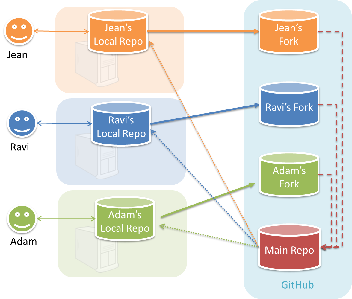
In the forking workflow, the 'official' version of the software is kept in a remote repo designated as the 'main repo'. All team members fork the main repo create pull requests from their fork to the main repo.
To illustrate how the workflow goes, let’s assume Jean wants to fix a bug in the code. Here are the steps:
- Jean creates a separate branch in her local repo and fixes the bug in that branch.
- Jean pushes the branch to her fork.
- Jean creates a pull request from that branch in her fork to the main repo.
- Other members review Jean’s pull request.
- If reviewers suggested any changes, Jean updates the PR accordingly.
- When reviewers are satisfied with the PR, one of the members (usually the team lead or a designated 'maintainer' of the main repo) merges the PR, which brings Jean’s code to the main repo.
- Other members, realizing there is new code in the upstream repo, sync their forks with the new upstream repo (i.e. the main repo). This is done by pulling the new code to their own local repo and pushing the updated code to their own fork.
Feature Branch Flow
Feature branch workflow is similar to forking workflow except there are no forks or PRs. Everyone is pushing/pulling from the same remote repo. The phrase feature branch is used because each new feature (or bug fix, or any other modification) is done in a separate branch.
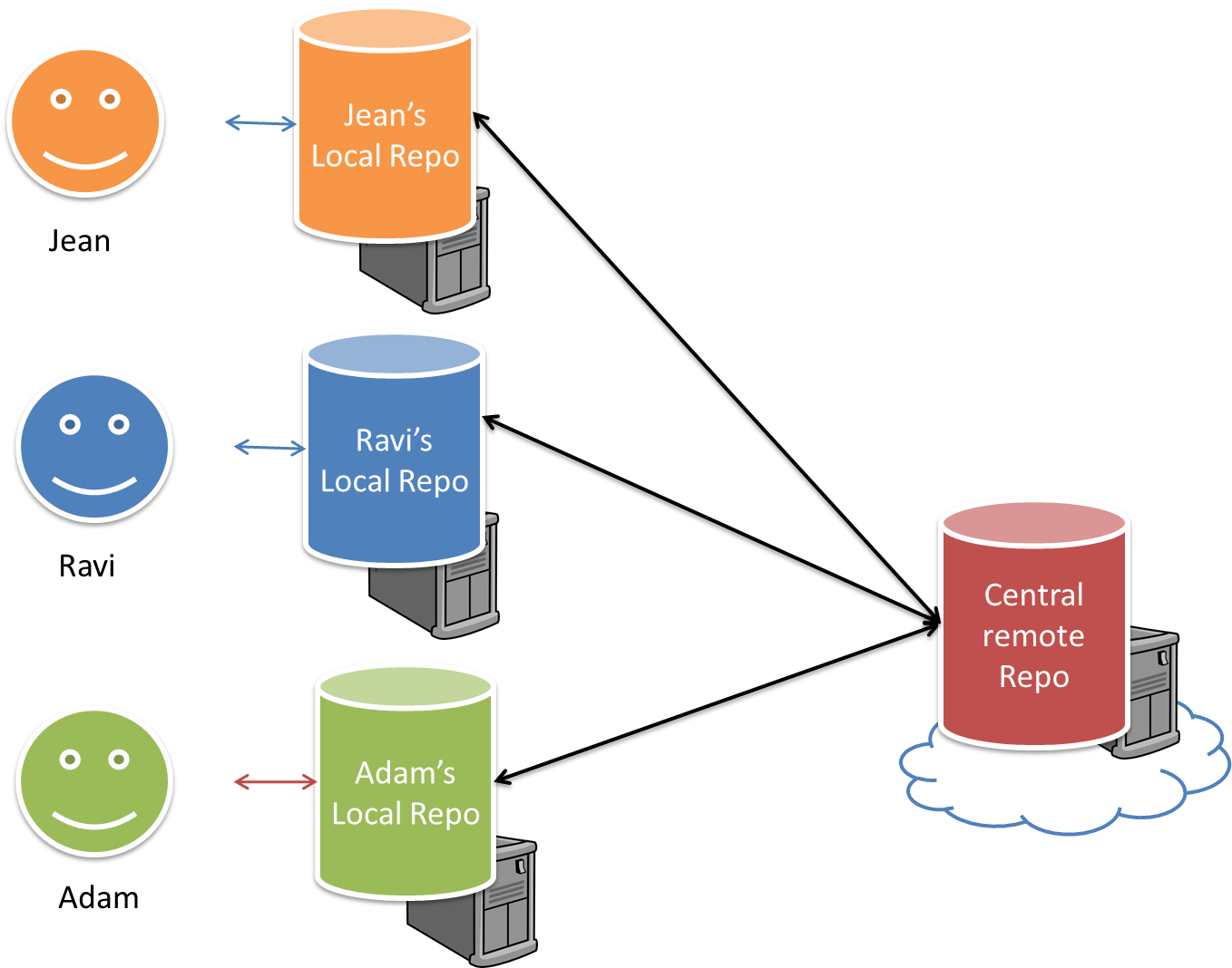
Centralized Flow
The centralized workflow is similar to the feature branch workflow except all changes are done in the master branch.
Project Planning
Work Breakdown Structure
A Work Breakdown Structure (WBS) depicts information about tasks and their details in terms of subtasks. When managing projects it is useful to divide the total work into smaller, well-defined units. Relatively complex tasks can be further split into subtasks. In complex projects a WBS can also include prerequisite tasks and effort estimates for each task.
📦 The high level tasks for a single iteration of a small project could look like the following:
| Task ID | Task | Estimated Effort | Prerequisite Task |
|---|---|---|---|
| A | Analysis | 1 man day | - |
| B | Design | 2 man day | A |
| C | Implementation | 4.5 man day | B |
| D | Testing | 1 man day | C |
| E | Planning for next version | 1 man day | D |
The effort is traditionally measured in man hour/day/month i.e. work that can be done by one person in one hour/day/month. The Task ID is a label for easy reference to a task. Simple labeling is suitable for a small project, while a more informative labeling system can be adopted for bigger projects.
📦 An example WBS for a project for developing a game.
| Task ID | Task | Estimated Effort | Prerequisite Task |
|---|---|---|---|
| A | High level design | 1 man day | - |
| B |
Detail design
|
2 man day
|
A |
| C |
Implementation
|
4.5 man day
|
|
| D | System Testing | 1 man day | C |
| E | Planning for next version | 1 man day | D |
All tasks should be well-defined. In particular, it should be clear as to when the task will be considered done.
📦 Some examples of ill-defined tasks and their better-defined counterparts:
| 👎 Not good | 👍 Better |
|---|---|
| more coding | implement component X |
| do research on UI testing | find a suitable tool for testing the UI |
Milestones
A milestone is the end of a stage which indicates a significant progress. We should take into account dependencies and priorities when deciding on the features to be delivered at a certain milestone.
📦 Each intermediate product release is a milestone.
In some projects, it is not practical to have a very detailed plan for the whole project due to the uncertainty and unavailability of required information. In such cases, we can use a high-level plan for the whole project and a detailed plan for the next few milestones.
📦 Milestones for the Minesweeper project, iteration 1
| Day | Milestones |
|---|---|
| Day 1 | Architecture skeleton completed |
| Day 3 | ‘new game’ feature implemented |
| Day 4 | ‘new game’ feature tested |
Buffers
A buffer is a time set aside to absorb any unforeseen delays. It is very important to include buffers in a software project schedule because effort/time estimations for software development is notoriously hard. However, do not inflate task estimates to create hidden buffers; have explicit buffers instead. Reason: With explicit buffers it is easier to detect incorrect effort estimates which can serve as a feedback to improve future effort estimates.
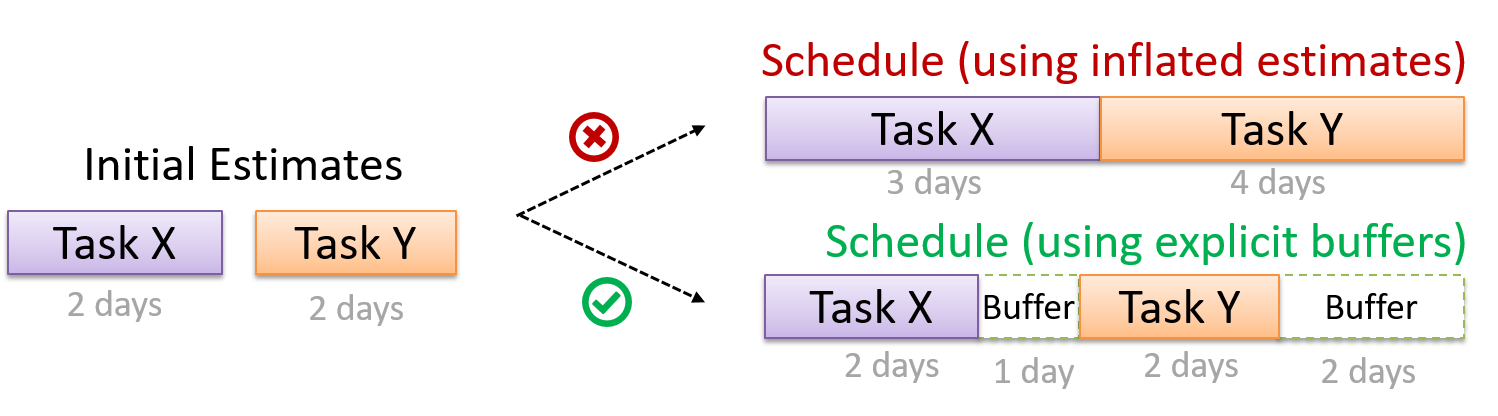
Issue Trackers
Keeping track of project tasks (who is doing what, which tasks are ongoing, which tasks are done etc.) is an essential part of project management. In small projects it may be possible to track tasks using simple tools as online spreadsheets or general-purpose/light-weight tasks tracking tools such as Trello. Bigger projects need more sophisticated task tracking tools.
Issue trackers (sometimes called bug trackers) are commonly used to track task assignment and progress. Most online project management software such as GitHub, SourceForge, and BitBucket come with an integrated issue tracker.
📦 A screenshot from the Jira Issue tracker software (Jira is part of the BitBucket project management tool suite):
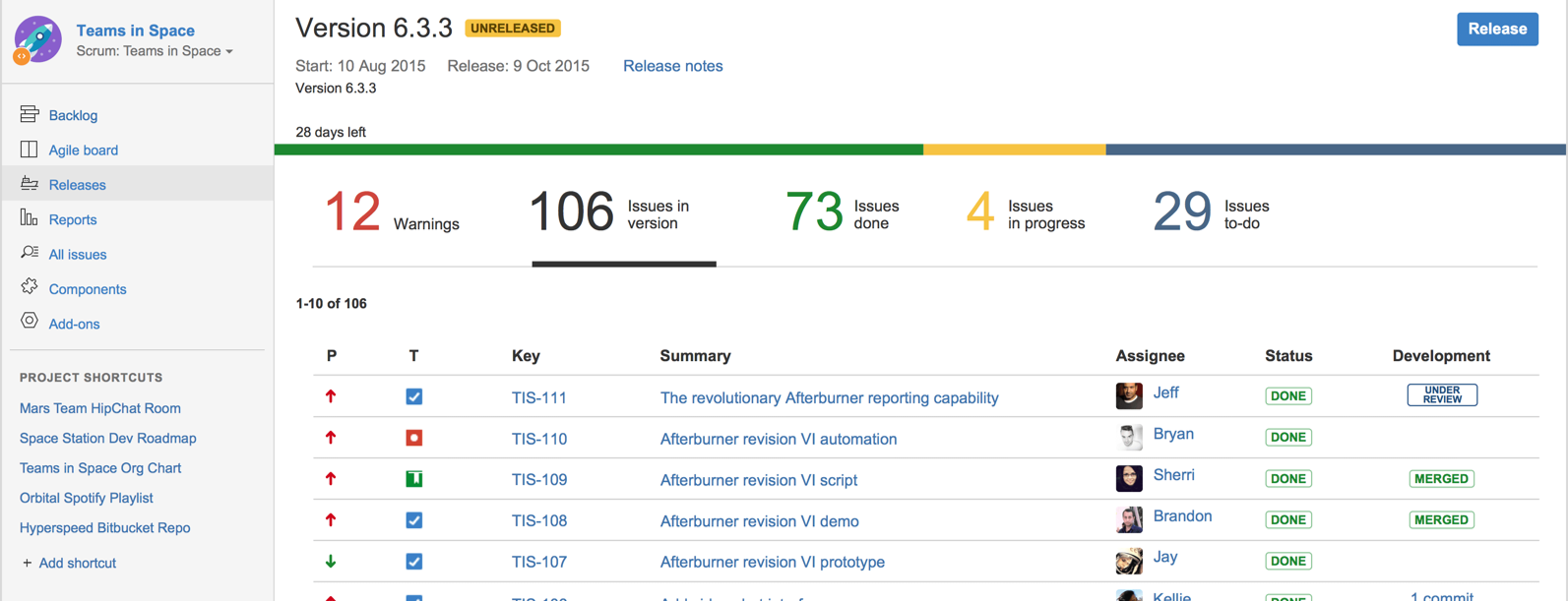
GANTT Charts
A Gantt chart is a 2-D bar-chart, drawn as time vs tasks (represented by horizontal bars).
📦 A sample Gantt chart:
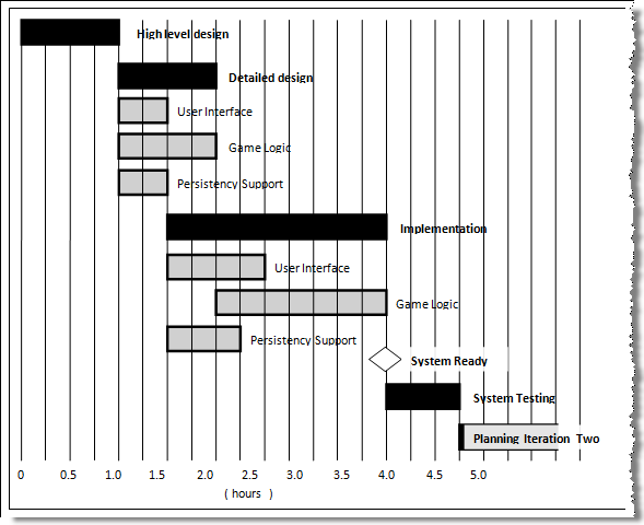
In a Gantt chart, a solid bar represents the main task, which is generally composed of a number of subtasks, shown as grey bars. The diamond shape indicates an important deadline/deliverable/milestone.
PERT Charts
PERT (Program Evaluation Review Technique) chart uses a graphical technique to show the order/sequence of tasks. It is based on a simple idea of drawing a directed graph in which:
- Node or vertex captures the effort estimation of a task, and
- Arrow depicts the precedence between tasks
📦 an example PERT chart for a simple software project
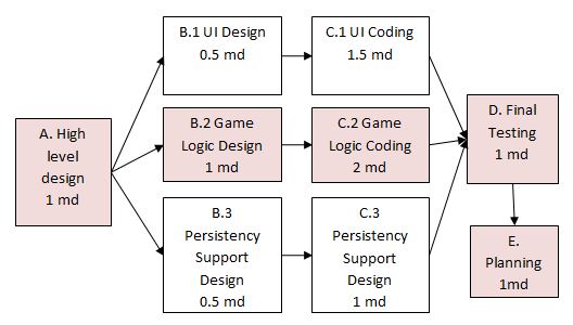
md = man days
A PERT chart can help determine the following important information:
- The order of tasks. In the example above,
Final Testingcannot begin until all coding of individual subsystems have been completed. - Which tasks can be done concurrently. In the example above, the various subsystem designs can start independently once the
High level designis completed. - The shortest possible completion time. In the example above, there is a path (indicated by the shaded boxes) from start to end that determines the shortest possible completion time.
- The Critical Path. In the example above, the shortest possible path is also the critical path.
Critical path is the path in which any delay can directly affect the project duration. It is important to ensure tasks on the critical path are completed on time.
Teamwork
Team Structures
Given below are three commonly used team structures in software development. Irrespective of the team structure, it is a good practice to assign roles and responsibilities to different team members so that someone is clearly in charge of each aspect of the project. In comparison, the ‘everybody is responsible for everything’ approach can result in more chaos and hence slower progress.
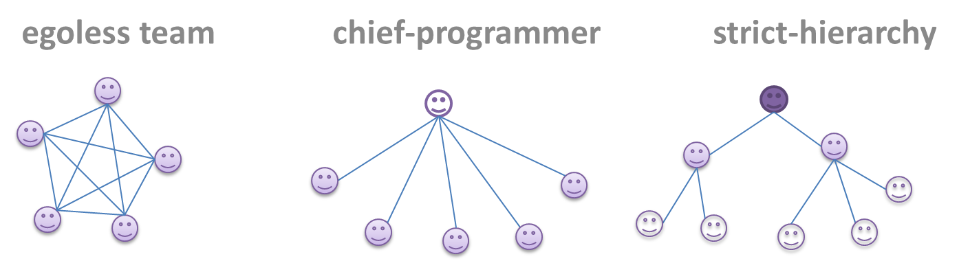
Egoless team
In this structure, every team member is equal in terms of responsibility and accountability. When any decision is required, consensus must be reached. This team structure is also known as a democratic team structure. This team structure usually finds a good solution to a relatively hard problem as all team members contribute ideas.
However, the democratic nature of the team structure bears a higher risk of falling apart due to the absence of an authority figure to manage the team and resolve conflicts.
Chief programmer team
Frederick Brooks proposed that software engineers learn from the medical surgical team in an operating room. In such a team, there is always a chief surgeon, assisted by experts in other areas. Similarly, in a chief programmer team structure, there is a single authoritative figure, the chief programmer. Major decisions, e.g. system architecture, are made solely by him/her and obeyed by all other team members. The chief programmer directs and coordinates the effort of other team members. When necessary, the chief will be assisted by domain specialists e.g. business specialists, database expert, network technology expert, etc. This allows individual group members to concentrate solely on the areas where they have sound knowledge and expertise.
The success of such a team structure relies heavily on the chief programmer. Not only must he be a superb technical hand, he also needs good managerial skills. Under a suitably qualified leader, such a team structure is known to produce successful work. .
Strict hierarchy team
In the opposite extreme of an egoless team, a strict hierarchy team has a strictly defined organization among the team members, reminiscent of the military or bureaucratic government. Each team member only works on his assigned tasks and reports to a single “boss”.
In a large, resource-intensive, complex project, this could be a good team structure to reduce communication overhead.
SDLC Process Models
Introduction
What
Software development goes through different stages such as requirements, analysis, design, implementation and testing. These stages are collectively known as the software development life cycle (SDLC). There are several approaches, known as software development life cycle models (also called software process models) that describe different ways to go through the SDLC. Each process model prescribes a "roadmap" for the software developers to manage the development effort. The roadmap describes the aims of the development stage(s), the artifacts or outcome of each stage as well as the workflow i.e. the relationship between stages.
Sequential Models
The sequential model, also called the waterfall model, models software development as a linear process, in which the project is seen as progressing steadily in one direction through the development stages. The name waterfall stems from how the model is drawn to look like a waterfall (see below).
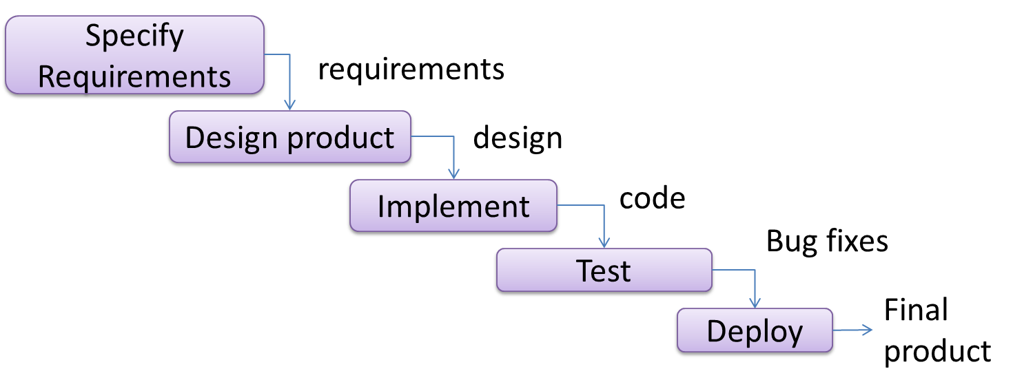
When one stage of the process is completed, it should produce some artifacts to be used in the next stage. For example, upon completion of the requirement stage a comprehensive list of requirements is produced that will see no further modifications. A strict application of the sequential model would require each stage to be completed before starting the next.
This could be a useful model when the problem statement that is well-understood and stable. In such cases, using the sequential model should result in a timely and systematic development effort, provided that all goes well. As each stage has a well-defined outcome, the progress of the project can be tracked with a relative ease.
The major problem with this model is that requirements of a real-world project are rarely well-understood at the beginning and keep changing over time. One reason for this is that users are generally not aware of how a software application can be used without prior experience in using a similar application.
Iterative Models
The iterative model (sometimes called iterative and incremental) advocates having several iterations of SDLC. Each of the iterations could potentially go through all the development stages, from requirement gathering to testing & deployment. Roughly, it appears to be similar to several cycles of the sequential model.
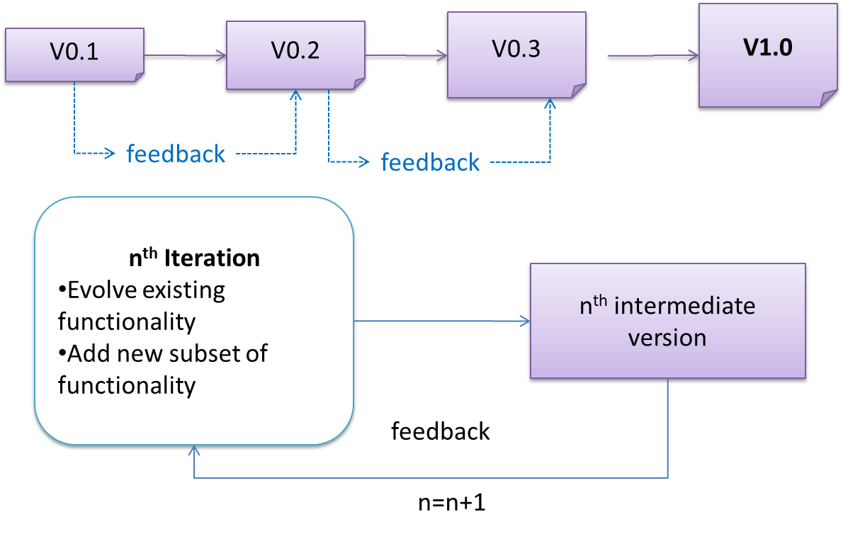
In this model, each of the iterations produces a new version of the product. Feedback on the version can then be fed to the next iteration. Taking the Minesweeper game as an example, the iterative model will deliver a fully playable version from the early iterations. However, the first iteration will have primitive functionality, for example, a clumsy text based UI, fixed board size, limited randomization etc. These functionalities will then be improved in later releases.
The iterative model can take a breadth-first or a depth-first approach to iteration planning.
- breadth-first: an iteration evolves all major components in parallel.
- depth-first: an iteration focuses on fleshing out only some components.
Most project use a mixture of breadth-first and depth-first iterations. Hence, the common phrase ‘an iterative and incremental process’.
Agile Models
In 2001, a group of prominent software engineering practitioners met and brainstormed for an alternative to documentation-driven, heavyweight software development processes that were used in most large projects at the time. This resulted in something called the agile manifesto (a vision statement of what they were looking to do).
We are uncovering better ways of developing software by doing it and helping others do it.
Through this work we have come to value:
- Individuals and interactions over processes and tools
- Working software over comprehensive documentation
- Customer collaboration over contract negotiation
- Responding to change over following a plan
That is, while there is value in the items on the right, we value the items on the left more.
Extract from the Agile Manifesto
Subsequently, some of the signatories of the manifesto went on to create process models that try to follow it. These processes are collectively called agile processes. Some of the key features of agile approaches are:
- Requirements are prioritized based on the needs of the user, are clarified regularly (at times almost on a daily basis) with the entire project team, and are factored into the development schedule as appropriate.
- Instead of doing a very elaborate and detailed design and a project plan for the whole project, the team works based on a rough project plan and a high level design that evolves as the project goes on.
- Strong emphasis on complete transparency and responsibility sharing among the team members. The team is responsible together for the delivery of the product. Team members are accountable, and regularly and openly share progress with each other and with the user.
There are a number of agile processes in the development world today. eXtreme Programming (XP) and Scrum are two of the well-known ones.
Example Process Models
XP
The following description was adapted from the XP home page, emphasis added:
Extreme Programming (XP) stresses customer satisfaction. Instead of delivering everything you could possibly want on some date far in the future, this process delivers the software you need as you need it.
XP aims to empower developers to confidently respond to changing customer requirements, even late in the life cycle.
XP emphasizes teamwork. Managers, customers, and developers are all equal partners in a collaborative team. XP implements a simple, yet effective environment enabling teams to become highly productive. The team self-organizes around the problem to solve it as efficiently as possible.
XP aims to improve a software project in five essential ways: communication, simplicity, feedback, respect, and courage. Extreme Programmers constantly communicate with their customers and fellow programmers. They keep their design simple and clean. They get feedback by testing their software starting on day one. Every small success deepens their respect for the unique contributions of each and every team member. With this foundation, Extreme Programmers are able to courageously respond to changing requirements and technology.
XP has a set of simple rules. XP is a lot like a jig saw puzzle with many small pieces. Individually the pieces make no sense, but when combined together a complete picture can be seen. This flow chart shows how Extreme Programming's rules work together.
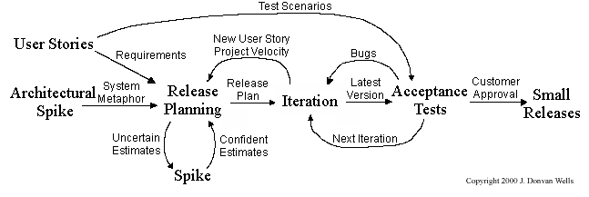
Pair programming, CRC cards, project velocity, and standup meetings are some interesting topics related to XP. Refer to extremeprogramming.org to find out more about XP.
Scrum
This description of Scrum was adapted from Wikipedia [retrieved on 18/10/2011], emphasis added:
Scrum is a process skeleton that contains sets of practices and predefined roles. The main roles in Scrum are:
- The Scrum Master, who maintains the processes (typically in lieu of a project manager)
- The Product Owner, who represents the stakeholders and the business
- The Team, a cross-functional group who do the actual analysis, design, implementation, testing, etc.
A Scrum project is divided into iterations called Sprints. A sprint is the basic unit of development in Scrum. Sprints tend to last between one week and one month, and are a timeboxed (i.e. restricted to a specific duration) effort of a constant length.
Each sprint is preceded by a planning meeting, where the tasks for the sprint are identified and an estimated commitment for the sprint goal is made, and followed by a review or retrospective meeting, where the progress is reviewed and lessons for the next sprint are identified.
During each sprint, the team creates a potentially deliverable product increment (for example, working and tested software). The set of features that go into a sprint come from the product backlog, which is a prioritized set of high level requirements of work to be done. Which backlog items go into the sprint is determined during the sprint planning meeting. During this meeting, the Product Owner informs the team of the items in the product backlog that he or she wants completed. The team then determines how much of this they can commit to complete during the next sprint, and records this in the sprint backlog. During a sprint, no one is allowed to change the sprint backlog, which means that the requirements are frozen for that sprint. Development is timeboxed such that the sprint must end on time; if requirements are not completed for any reason they are left out and returned to the product backlog. After a sprint is completed, the team demonstrates the use of the software.
Scrum enables the creation of self-organizing teams by encouraging co-location of all team members, and verbal communication between all team members and disciplines in the project.
A key principle of Scrum is its recognition that during a project the customers can change their minds about what they want and need (often called requirements churn), and that unpredicted challenges cannot be easily addressed in a traditional predictive or planned manner. As such, Scrum adopts an empirical approach—accepting that the problem cannot be fully understood or defined, focusing instead on maximizing the team’s ability to deliver quickly and respond to emerging requirements.
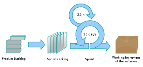
Daily Scrum is another key scrum practice. The description below was adapted from https://www.mountaingoatsoftware.com (emphasis added):
In Scrum, on each day of a sprint, the team holds a daily scrum meeting called the "daily scrum.” Meetings are typically held in the same location and at the same time each day. Ideally, a daily scrum meeting is held in the morning, as it helps set the context for the coming day's work. These scrum meetings are strictly time-boxed to 15 minutes. This keeps the discussion brisk but relevant.
...
During the daily scrum, each team member answers the following three questions:
- What did you do yesterday?
- What will you do today?
- Are there any impediments in your way?
...
The daily scrum meeting is not used as a problem-solving or issue resolution meeting. Issues that are raised are taken offline and usually dealt with by the relevant subgroup immediately after the meeting.
(This is not an endorsement of the product mentioned in the video)
Unified Process
The unified process is developed by the Three Amigos - Ivar Jacobson, Grady Booch and James Rumbaugh (the creators of UML).
The unified process consists of four phases: inception, elaboration, construction and transition. The main purpose of each phase can be summarized as follows:
| Phase | Activities | Typical Artifacts |
|---|---|---|
| Inception |
|
|
| Elaboration |
|
|
| Construction |
|
|
| Transition |
|
|
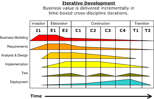
Given above is a visualization of a project done using the Unified process (source: Wikipedia). As the diagram shows, a phase can consist of several iterations. Each vertical column (labeled “I1” “E1”, “E2”, “C1”, etc.) represents a single iteration. Each of the iterations consists of a set of ‘workflows’ such as ‘Business modeling’, ‘Requirements’, ‘Analysis & Design’ etc. The shaded region indicates the amount of resource and effort spent on a particular workflow in a particular iteration.
Unified process is a flexible and customizable process model framework rather than a single fixed process. For example, the number of iterations in each phase, definition of workflows, and the intensity of a given workflow in a given iteration can be adjusted according to the nature of the project. Take the Construction Phase, to develop a simple system, one or two iterations would be sufficient. For a more complicated system, multiple iterations will be more helpful. Therefore, the diagram above simply records a particular application of the UP rather than prescribe how the UP is to be applied. However, this record can be refined and reused for similar future projects.
More
CMMI
CMMI (Capability Maturity Model Integration) is a process improvement approach defined by Software Engineering Institute at Carnegie Melon University. CMMI provides organizations with the essential elements of effective processes, which will improve their performance. -- adapted from http://www.sei.cmu.edu/cmmi/
CMMI defines five maturity levels for a process and provides criteria to determine if the process of an organization is at a certain maturity level. The diagram below [taken from Wikipedia] gives an overview of the five levels.
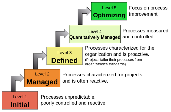
SECTION: TOOLS
UML
Class Diagrams
Introduction
What
UML class diagrams describe the structure (but not the behavior) of an OOP solution. These are possibly the most often used diagrams in the industry and an indispensable tool for an OO programmer.
📦 An example class diagram:
Classes
What
The basic UML notations used to represent a class:
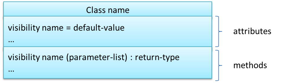
📦 A Table class shown in UML notation:
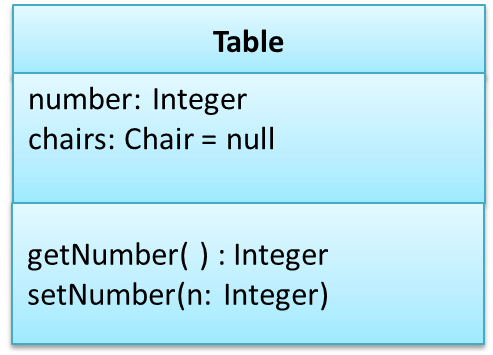
class Table{

    Integer number;
    Chair[] chairs = null;

    Integer getNumber(){
        ...
    }

    void setNumber(Integer n){
        ...
    }
}
The 'Operations' compartment and/or the 'Attributes' compartment may be omitted if such details are not important for the task at hand. 'Attributes' always appear above the 'Operations' compartment. All operations should be in one compartment rather than each operation in a separate compartment. Same goes for attributes.
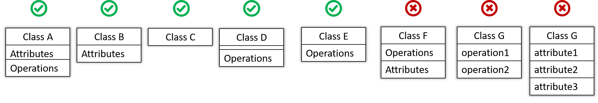
The visibility of attributes and operations is used to indicate the level of access allowed for each attribute or operation. The types of visibility and their exact meanings depend on the programming language used. Here are some common visibilities and how they are indicated in a class diagram:
+:public-:private#:protected~:package private
📦 Table class with visibilities shown:
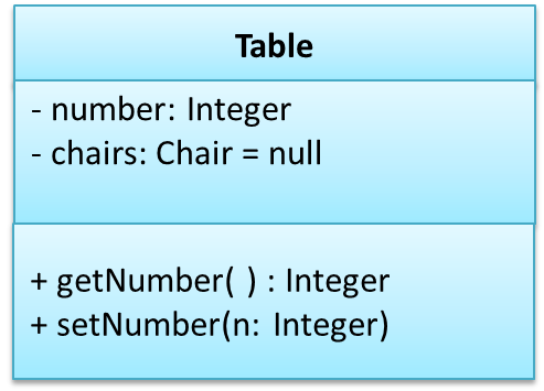
Associations
Basic
We use a solid line to show an association between two classes.
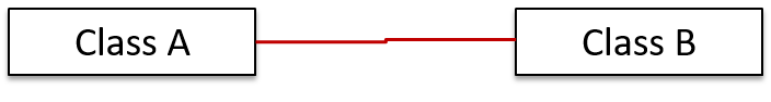
📦 This example shows an association between the Admin class and the Student class:
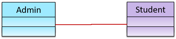
Navigability
We use arrow heads to indication the navigability of an association.
📦 Logic is aware of Minefield, but Minefield is not aware of Logic
class Logic{
    Minefield minefield;
}

class Minefield{
    ...
}
Navigability can be shown in class diagrams as well as object diagrams.
Roles
Association Role labels are used to indicate the role played by the classes in the association.
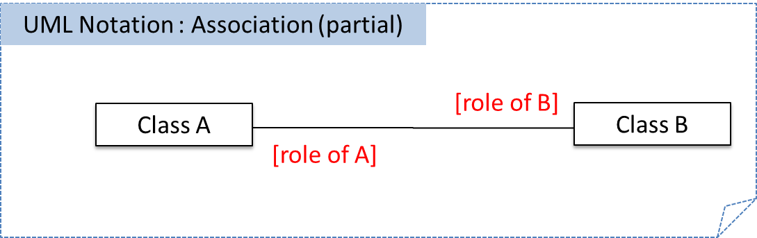
📦 This association represents a marriage between a Man object and a Woman object. The respective roles played by objects of these two classes are husband and wife.
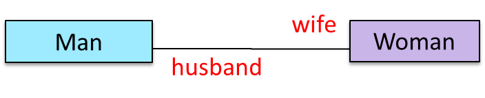
Note how the variable names match closely with the association roles.
class Man{
    Woman wife;
}

class Woman{
    Man husband;
}
📦 The role of Student objects in this association is charges (i.e. Admin is in charge of students)
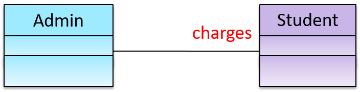
class Admin{
    List<Student> charges;
}
Labels
Association labels describe the meaning of the association. The arrow head indicates the direction in which the label is to be read.

📦 In this example, the same association is described using two different labels.
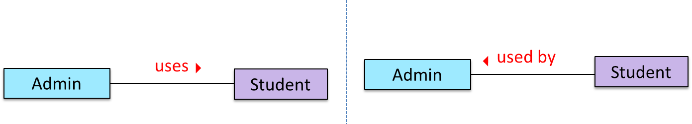
- Diagram on the left:
Adminclass is associated withStudentclass because anAdminobject uses aStudentobject. - Diagram on the right:
Adminclass is associated withStudentclass because aStudentobject is used by anAdminobject.
Multiplicity
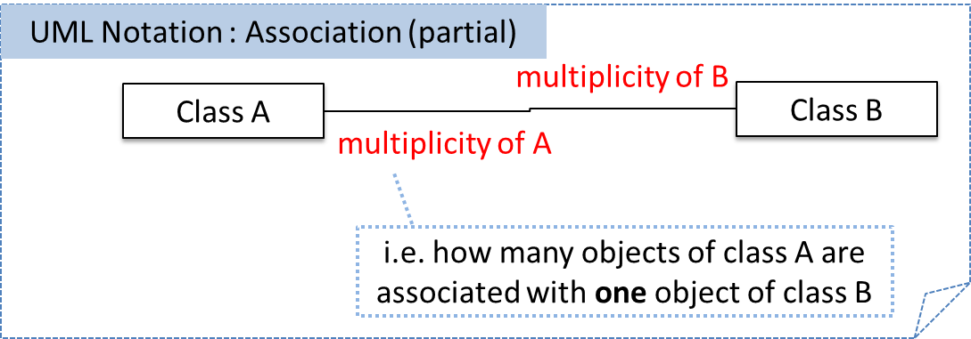
Commonly used multiplicities:
0..1: optional, can be linked to 0 or 1 objects1: compulsory, must be linked to one object at all times.*: can be linked to 0 or more objects.n..m: the number of linked objects must bentominclusive
📦 In the diagram below, an Admin object administers (in charge of) any number of students but a Student object must always be under the charge of exactly one Admin object
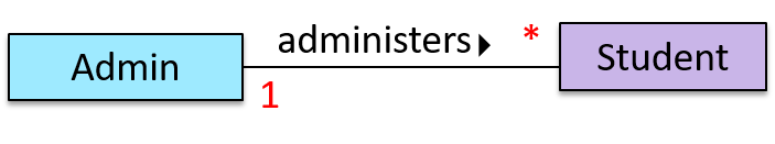
📦 In the diagram below,
- Each student must be supervised by exactly one professor. i.e. There cannot be a student who doesn't have a supervisor or has multiple supervisors.
- A professor cannot supervise more than 5 students but can have no students to supervise.
- An admin can handle any number of professors and any number of students, including none.
- A professor/student can be handled by any number of admins, including none.
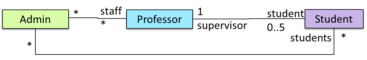
Associations as Attributes
Associations as Attributes
🏆 Can show an association as an attribute ![]()
An association can be shown as an attribute instead of a line.
Association multiplicities and the default value too can be shown as part of the attribute using the following notation. Both are optional.
name: type [multiplicity] = default value
📦 The diagram below depicts a multi-player Square Game being played on a board comprising of 100 squares. Each of the squares may be occupied with any number of pieces, each belonging to a certain player.
A Piece may or may not be on a Square. Note how that association can be replaced by an isOn attribute of the Piece class. The isOn attribute can either be null or
hold a reference to a Square object, matching the 0..1 multiplicity of the association it replaces. The default value is null.
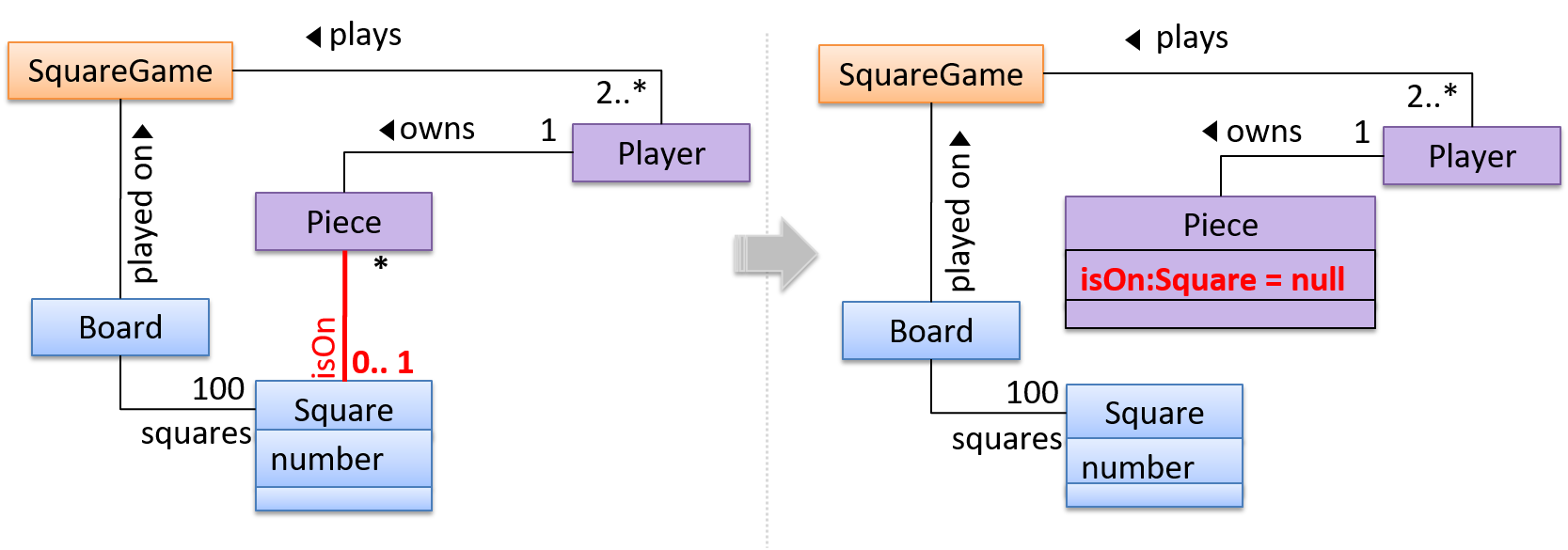
The association that a Board has 100 Sqaures can be shown in either of these two ways:
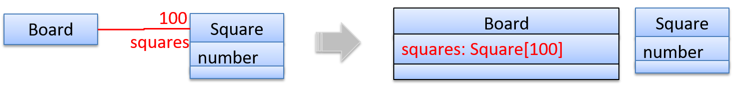
Enumerations
What
Notation:
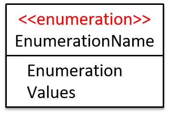
📦 In the class diagram below, there are two enumerations in use:
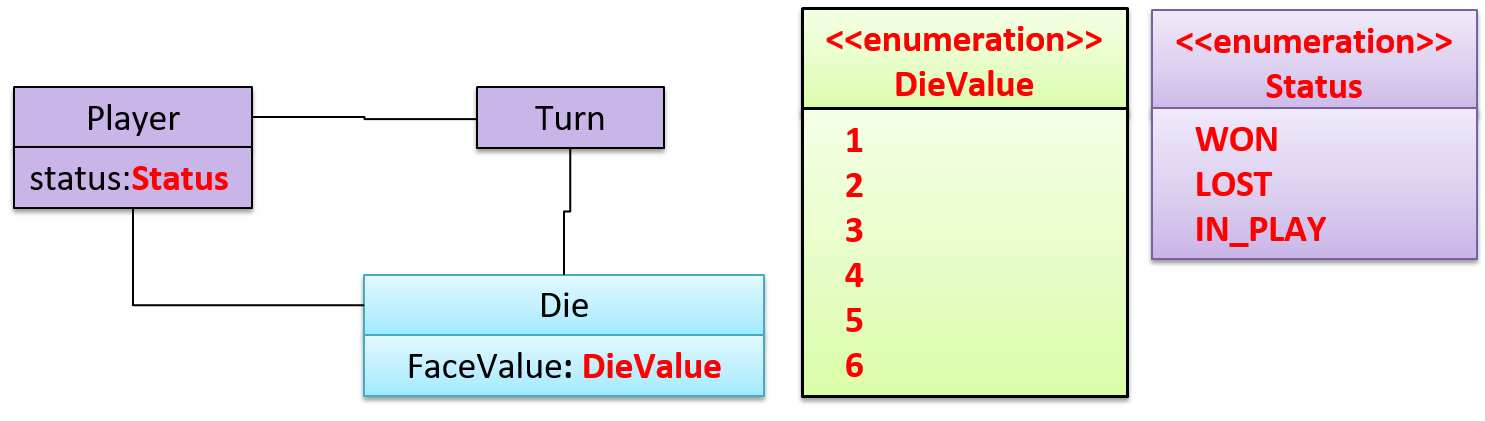
Class Level Members
Class-Level Members
In UML class diagrams, underlines denote class-level attributes and variables.
📦 In the class below, totalStudents attribute and the getTotalStudents method are class-level.
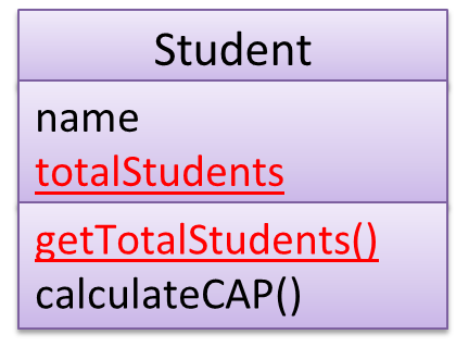
Association Classes
Association Classes
Association classes are denoted as a connection to an association link using a dashed line as shown below.
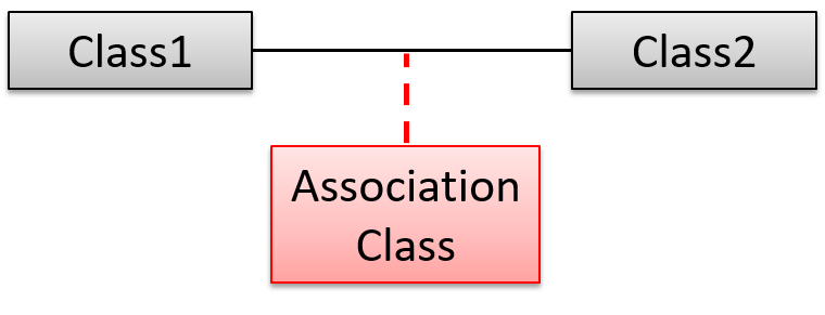
📦 In this example Loan is an association class because it stores information about the borrows association between the User and the Book.
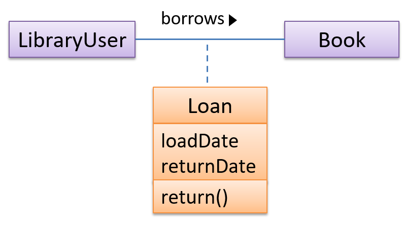
Composition
Composition
UML uses a solid diamond symbol to denote composition.
Notation:
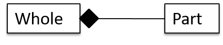
📦 A Book consists of Chapter objects. When the Book object is destroyed, its Chapter objects are destroyed too.
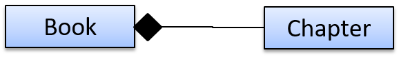
Aggregation
Aggregation
UML uses a hollow diamond is used to indicate an aggregation.
📦 Example:
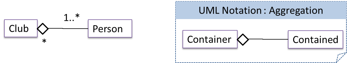
Class Inheritance
Inheritance
You can use a triangle and a solid line (not to be confused with an arrow) to indicate class inheritance.
Notation:
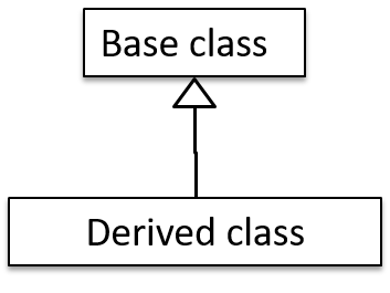
📦 Examples: The Car class inherits from the Vehicle class. The Cat and Dog classes inherit from the Pet class.
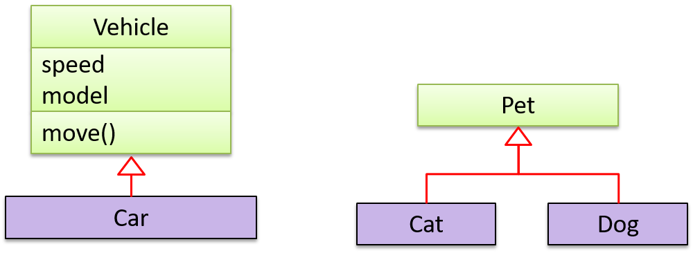
Interfaces
Interfaces
An interface is shown similar to a class with an additional keyword << interface >>. When a class implements an interface, it is shown similar to class inheritance except a dashed line is used instead of a solid line.
📦 The AcademicStaff and the AdminStaff classes implement the SalariedStaff interface.
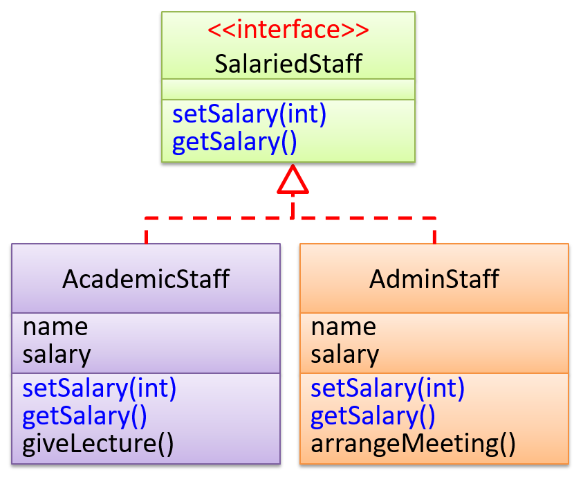
Abstract Classes
What
We can use italics or {abstract} keyword to denote abstract classes/methods.
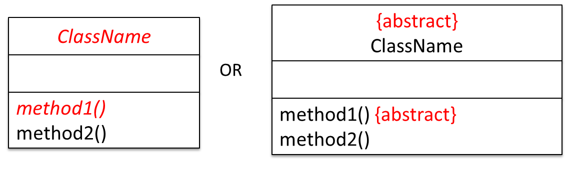
Example:
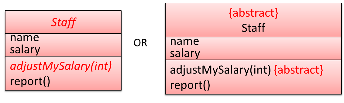
Object Diagrams
Introduction
An object diagram shows an object structure at a given point of time.
Objects
Notation:
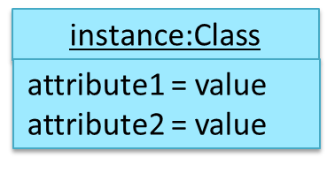
Notes:
- The class name and object name e.g.
car1:Carare underlined. objectName:ClassNameis meant to say 'an instance ofClassNameidentified asobjectName'.- Unlike classes, there is no compartment for methods.
- Attributes compartment can be omitted if it is not relevant to the task at hand.
- Object name can be omitted too e.g.
:Carwhich is meant to say 'an unnamed instance of a Car object'.
📦 Some example objects:
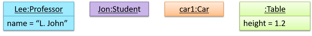
What
A solid line indicates an association between two objects.
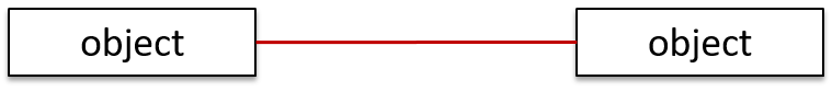
📦 An example object diagram showing two associations:
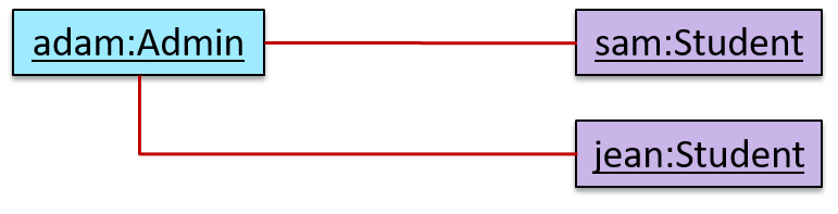
Sequence Diagrams
Introduction
A UML sequence diagram captures the interactions between multiple objects for a given scenario.
📦 Some exmaple sequence diagrams:


Basic
Notation:
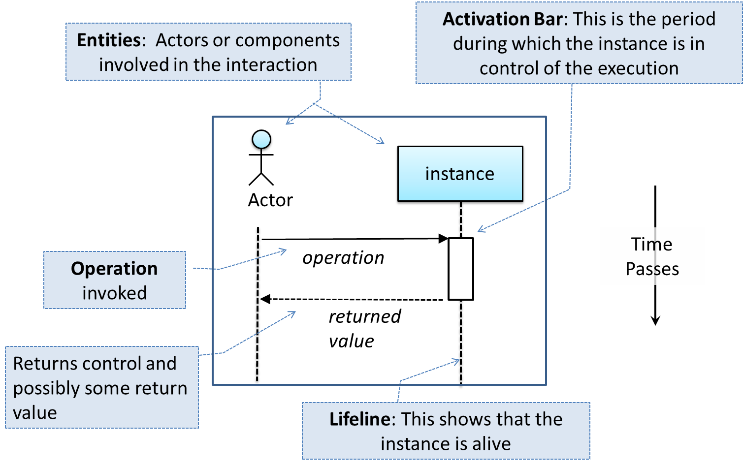
📦 This sequence diagram shows some interactions between a human user and the Text UI of a
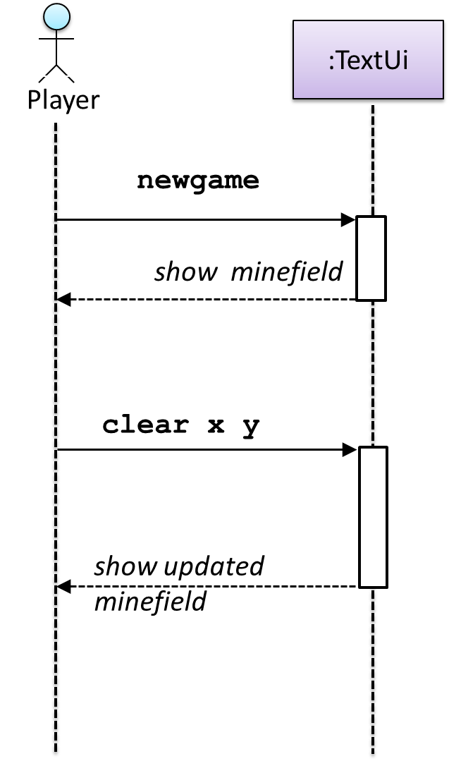
The player runs the newgame action on the TextUi object which results in the TextUi showing the minefield to the player. Then, the player runs the clear x y command; in response, the TextUi object shows the updated minefield.
The :TextUi in the above example denotes an unnamed instance of the class TextUi. If there were two instances of TextUi in the diagram, they can be distinguished by naming them e.g. TextUi1:TextUi and TextUi2:TextUi.
Arrows representing method calls should be solid arrows while those representing method returns should be dashed arrows.
Note that unlike in Object Diagrams, the class/object name is not underlined in sequence diagrams.
❌ [Common notation error] Activation bar too long: The activation bar of a method cannot start before the method call arrives and a method cannot remain active after the method had returned. In the two sequence diagrams below, the one on the left commits this error because the activation bar starts before the method Foo#xyz() is called and remains active after the method returns.
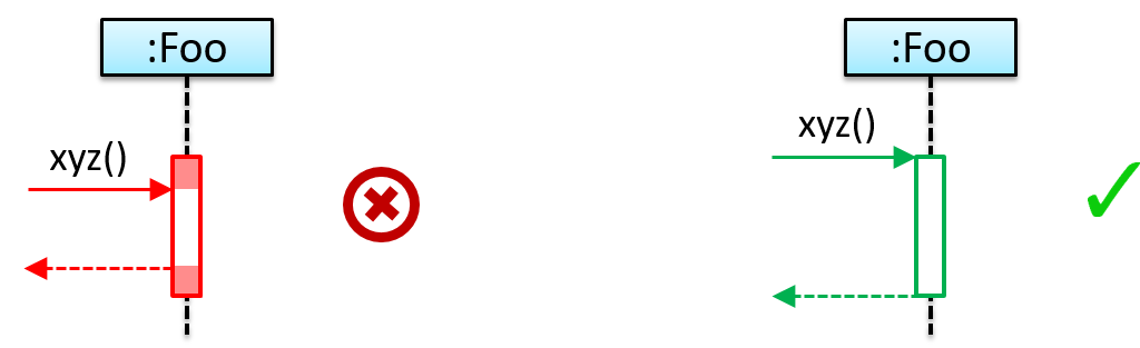
❌ [Common notation error] Broken activation bar: The activation bar should remain unbroken from the point the method is called until the method returns. In the two sequence diagrams below, the one on the left commits this error because the activation bar for the method Foo#abc() is not contiguous, but appears as two pieces instead.
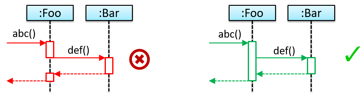
Object Creation
Notation:
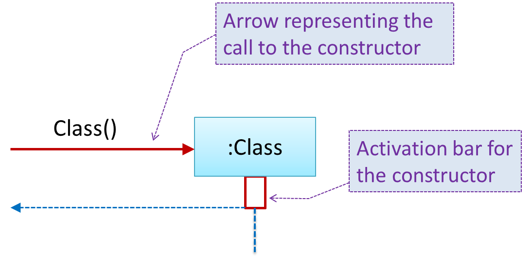
- The arrow that represents the constructor arrives at the side of the box representing the instance.
- The activation bar represents the period the constructor is active.
📦 The Logic object creates a Minefield object.
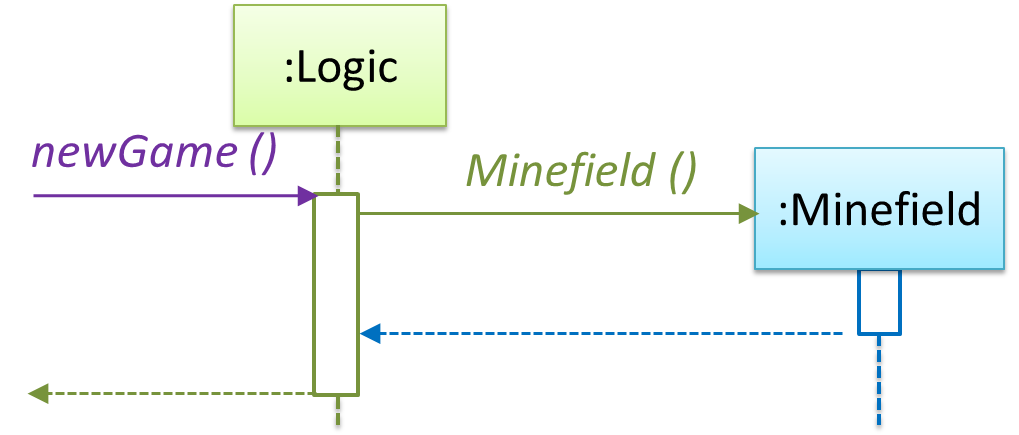
Object Deletion
UML uses an X at the end of the lifeline of an object to show it's deletion.
💡 Although object deletion is not that important in languages such as Java that support automatic memory management, you can still show object deletion in UML diagrams to indicate the point at which the object ceases to be used.
Notation:
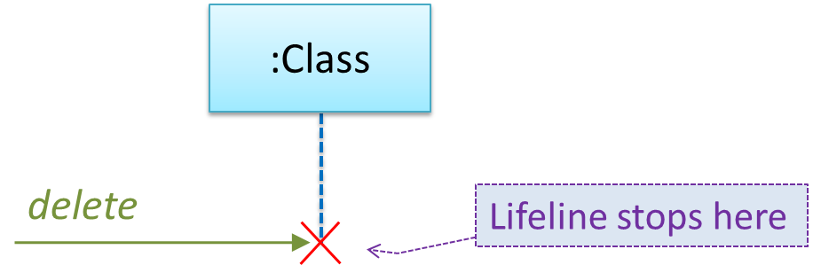
📦 Note how the diagrams shows the deletion of the Minefield object
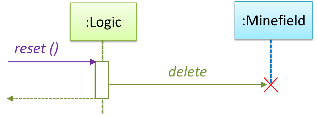
Loops
Notation:
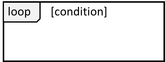
📦 The Player calls the mark x,y command or clear x y command repeatedly until the game is won or lost.
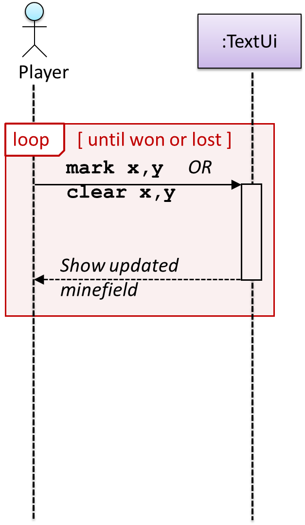
Self Invocation
UML can show a method of an object calling another of its own methods.
Notation:
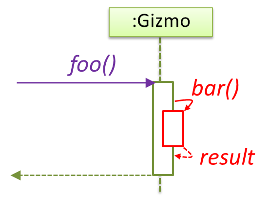
📦 The markCellAt(...) method of a Logic object is calling its own updateState(...) method.
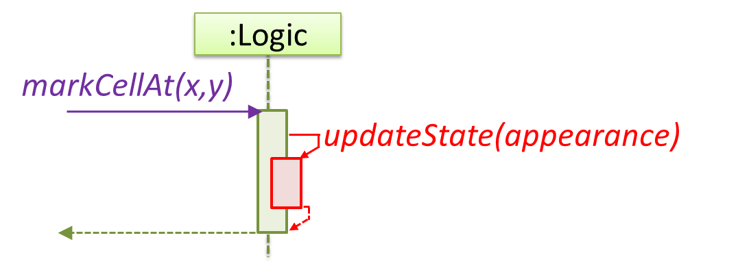
📦 In this variation, the Book#write() method is calling the Chapter#getText() method which in turn does a call back by calling the getAuthor() method of the calling object.
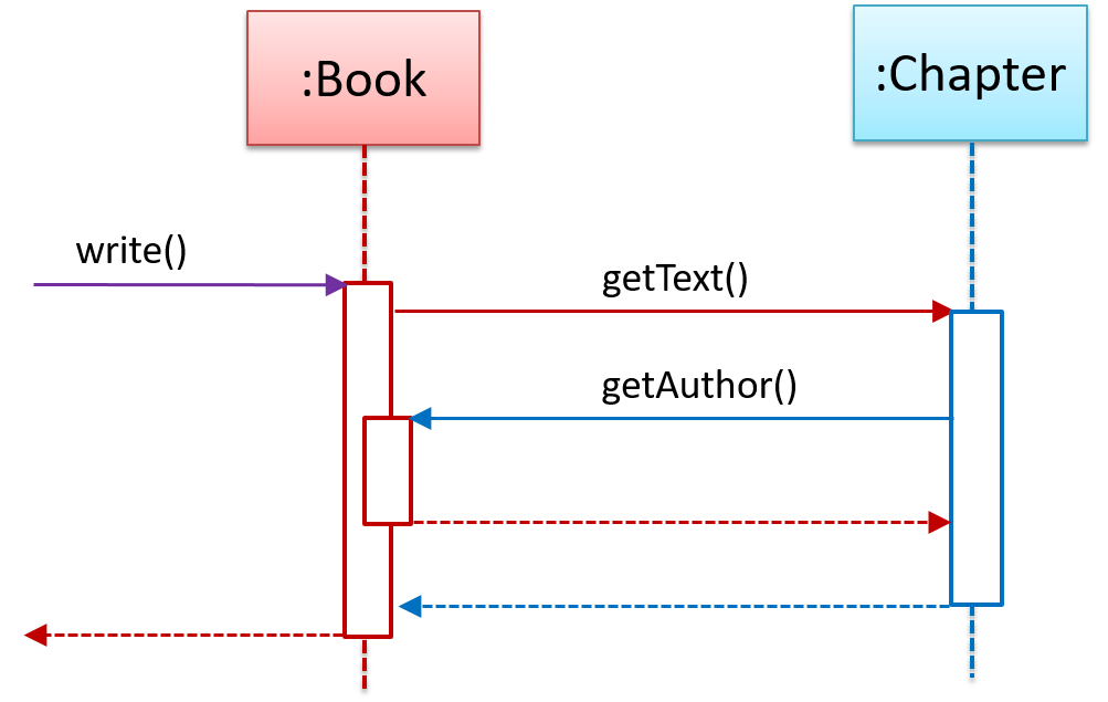
Alternative Paths
UML uses alt frames to indicate alternative paths.
Notation:
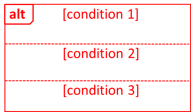
📦 Minefield calls the Cell#setMine if the cell is supposed to be a mined cell, and calls the Cell:setMineCount(...) method otherwise.
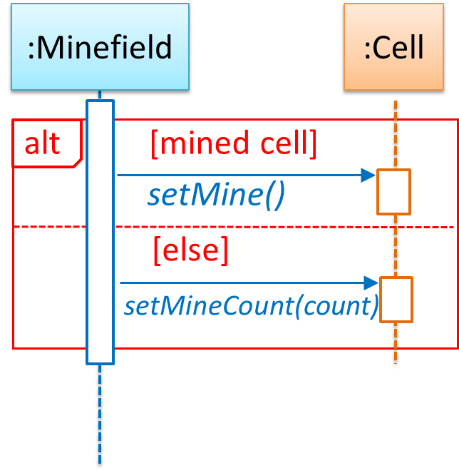
Optional Paths
UML uses opt frames to indicate optional paths.
Notation:

📦 Logic#markCellAt(...) calls Timer#start() only if it is the first move of the player.
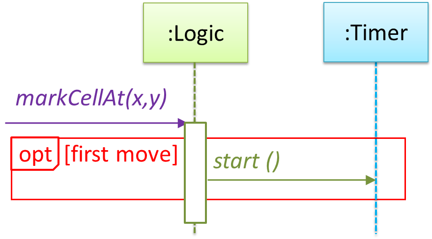
Parallel Paths
UML uses par frames to indicate parallel paths.
Notation:
📦 Logic is calling methods CloudServer#poll() and LocalServer#poll() in parallel.
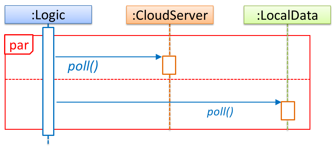
💡 If you show parallel paths in a sequence diagram, the corresponding Java implementation is likely to be multi-threaded because a normal Java program cannot do multiple things at the same time.
Reference Frames
UML uses ref frame to allow a segment of the interaction to be omitted and shown as a separate sequence diagram. Reference frames help us to break complicated sequence diagrams into multiple parts or simply to omit details we are not interested in showing.
Notation:
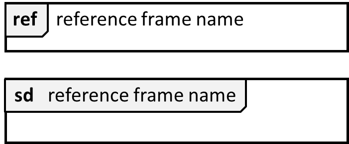
📦 The details of the get minefield appearance interactions have been omitted from the diagram.
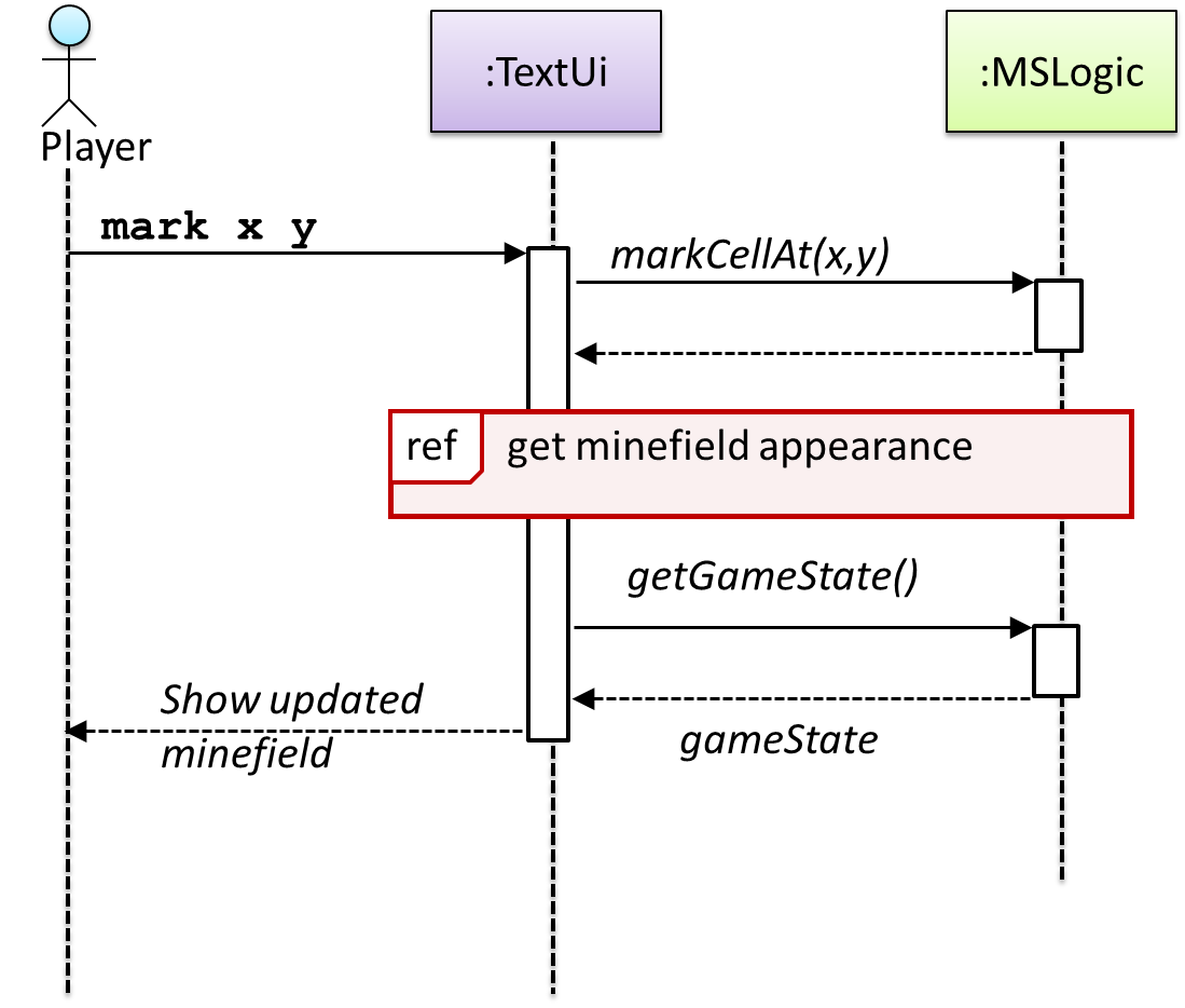
Those details are shown in a separate sequence diagram given below.
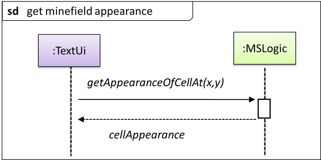
Minimal Notation
To reduce clutter, activation bars and return arrows may be omitted if they do not result in ambiguities or loss of information. Informal operation descriptions such as those given in the example below can be used, if more precise details are not required for the task at hand.
📦 A minimal sequence diagram
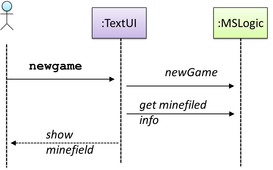
Activity Diagrams
Introduction
Introduction
A UML Activity diagram (AD) can model workflows.
An example activity diagram:
[source:wikipeida]
Basic Notations
Linear Paths
An activity diagram (AD) captures an activity of actions and control flows that makes up the activity.
- An action is a single step in an activity. It is shown as a rectangle with rounded corners.
- A control flow shows the flow of control from one action to the next. It is shown by drawing a line with an arrow-head to show the direction of the flow.
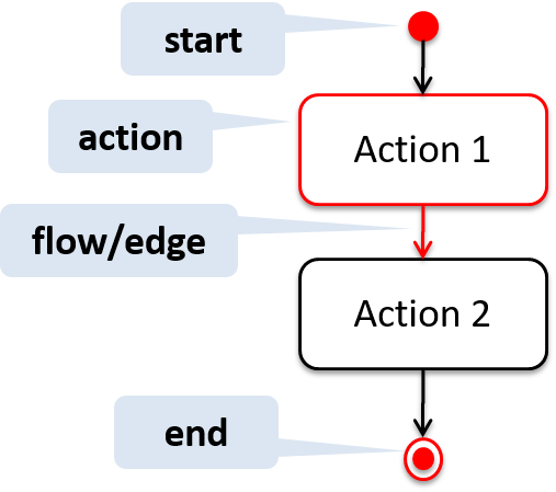
Note the slight difference between the start node and the end node which represent the start and the end of the activity, respectively.
📦 This activity diagram shows the action sequence of the activity a passenger rides the bus:
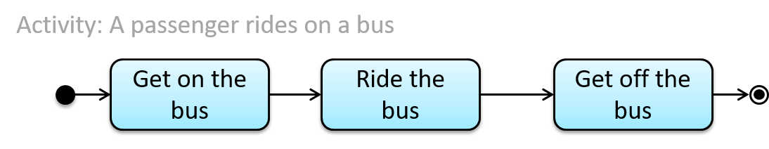
Alternate Paths
A branch node shows the start of alternate paths. Each control flow exiting a branch node has a guard condition : a boolean condition that should be true for execution to take that path. Only one of the guard condition can be true at any time.
A merge node shows the end of alternate paths.
Both branch nodes and merge nodes are diamond shapes. Guard conditions must be in square brackets.
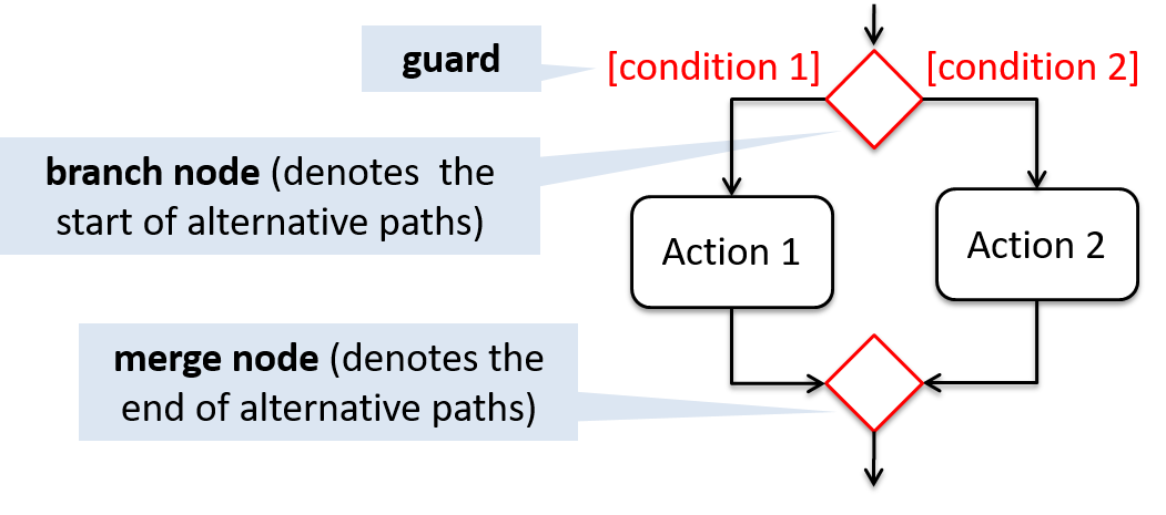
📦 The AD below shows alternate paths involved in the workflow of the activity shop for product:
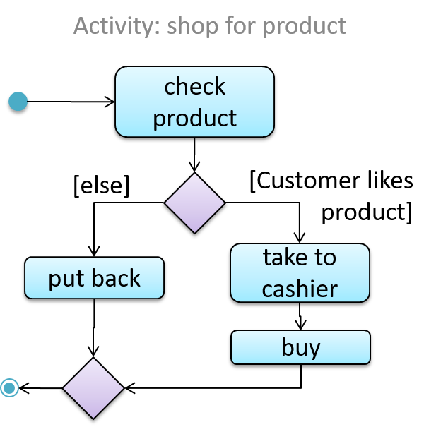
Parallel Paths
Fork nodes indicate the start of
Join nodes indicate the end of parallel paths.
Both have the same notation: a bar.
In a
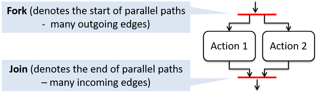
📦 In this activity diagram (from an online shop website) the actions User browsers products and System records browsing data happen in parallel. Both of them need to finish before the log out action can take place.
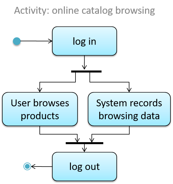
Rakes
The rake notation is used to indicate that a part of the activity is given as a separate diagram.
📦 Here is the AD for a game of ‘Snakes and Ladders’.
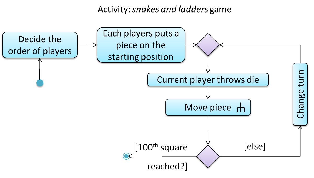
The rake symbol (in the Move piece action above) is used to show that the action is described in another subsidiary activity diagram elsewhere. That diagram is given below.
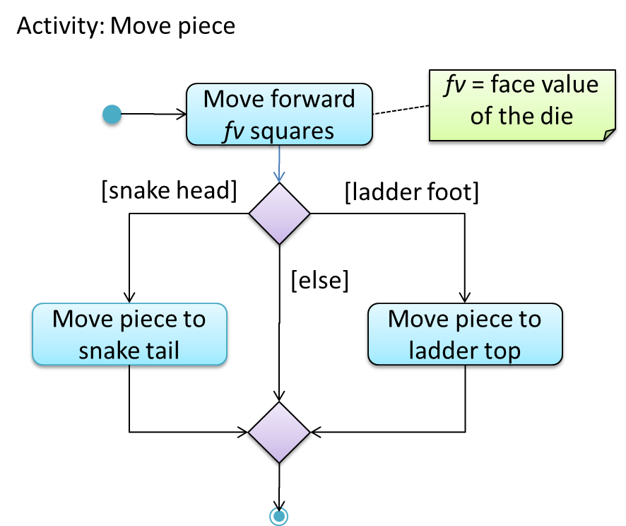
Swimlanes
It is possible to partition an activity diagram to show who is doing which action. Such partitioned activity diagrams are sometime called swimlane diagrams.
📦 A simple example of a swimlane diagram:
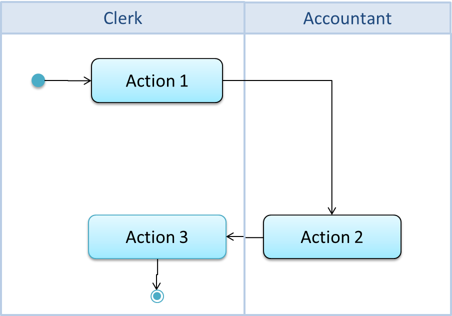
Notes
Notes
UML notes can augment UML diagrams with additional information. These notes can be shown connected to a particular element in the diagram or can be shown without a connection. The diagram below shows examples of both.
📦 Example:
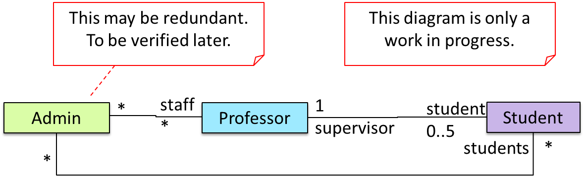
Constraints
A constraint can be given inside a note, within curly braces. Natural language or a formal notation such as OCL (Object Constraint Language) may be used to specify constraints.
📦 Example:
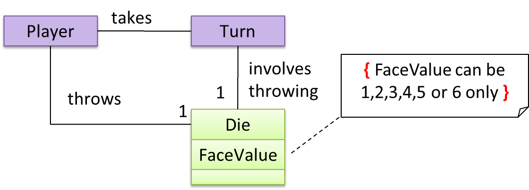
Miscellaneous
Object vs Class Diagrams
Compared to the notation for a class diagrams, object diagrams differ in the following ways:
- Shows objects instead of classes:
- Instance name may be shown
- There is a
:before the class name - Instance and class names are underlined
- Methods are omitted
- Multiplicities are omitted
Furthermore, multiple object diagrams can correspond to a single class diagram.
📦 Both object diagrams are derived from the same class diagram shown earlier. In other words, each of these object diagrams shows ‘an instance of’ the same class diagram.
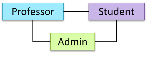
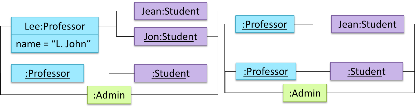
Intellij IDEA
Running Intellij IDEA for the First Time
A little bit more detailed explanation (from CodeLaunch) with some additional info at the end.
Importing a Project to Intellij IDEA
Some useful navigation shortcuts:
- Quickly locate a file by name.
- Go to the definition of a method from where it is used.
- Go back to the previous location.
- View the documentation of a method from where the method is being used, without navigating to the method itself.
- Find where a method/field is being used.
Productivity Shortcuts
Debugging: Basic
This video (from LaunchCode) gives a pretty good explanation of how to use the Intellij IDEA debugger.
- Intellij IDEA Documentation: Debugging Basics - Can be used as a reference document when you want to recall how to use a debugging feature.
Refactoring
This video explains how to automate the 'Extract parameter' refactoring using Intellij IDEA. Most other refactorings available works similarly. i.e. select the code to refactor → find the refactoring in the context menu or use the keyboard shortcut.
Here's another video explaining how to change a method signature as part of refactoring.
- Introduction to Refactoring (in Intellij IDEA) : An article on refactorings available in Intellij IDEA.
Git and GitHub
Soon you are going to take your first step in using Git. If you would like to see a quick overview of the full Git landscape before jumping in, watch the video below.
Install SourceTree which is Git + a GUI for Git.
Suppose you want to create a repository in an empty directory things
Windows: Click File → Clone/New…. Click on Create button.
Mac: New... → Create New Repository.
Enter the location of the directory (Windows version shown below) and click Create.
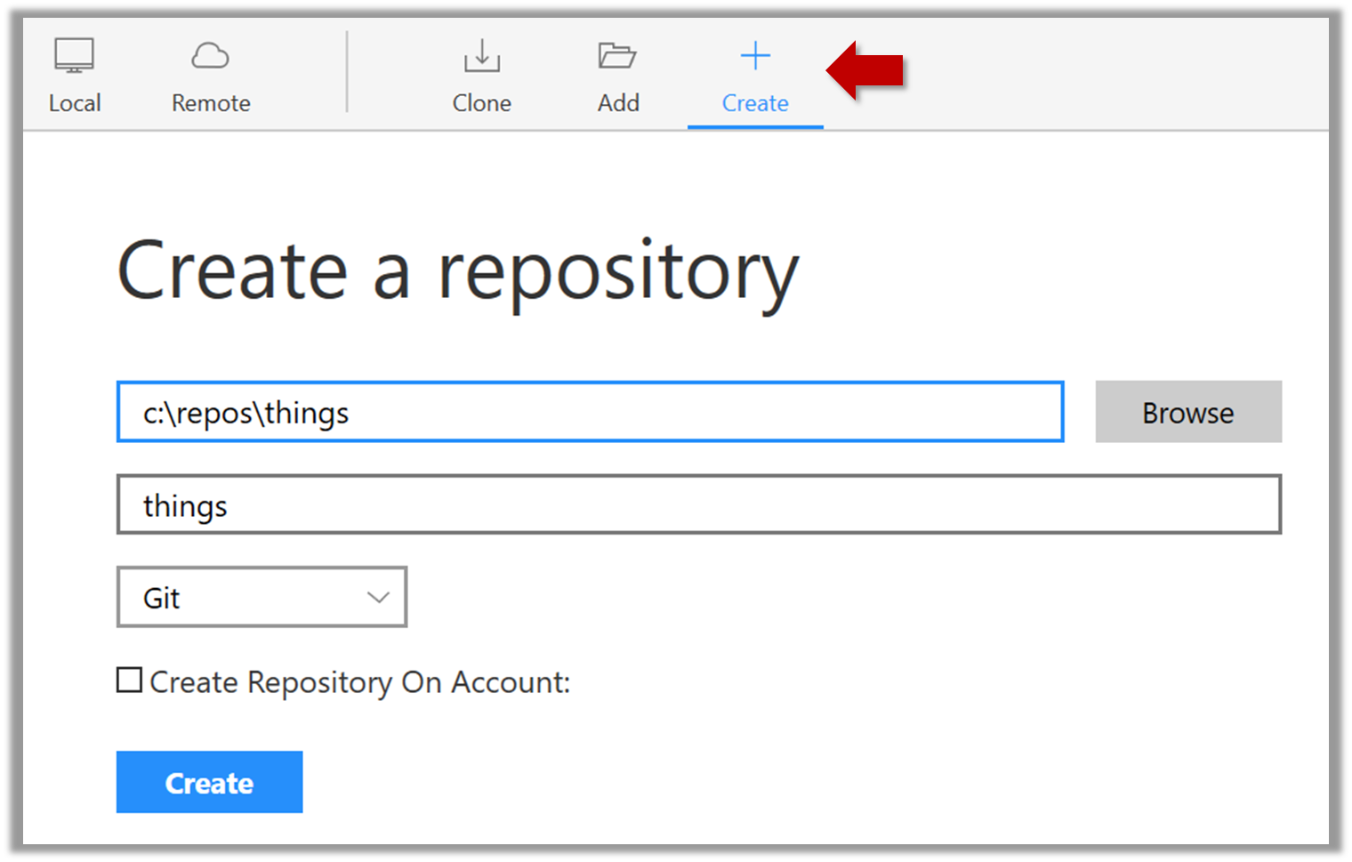
Go to the things folder and observe how a hidden folder .git has been created.
Note: If you are on Windows, you might have to configure Windows Explorer to show hidden files.
Open a Git Bash Terminal.
If you installed SourceTree, you can click the Terminal button to open a GitBash terminal.
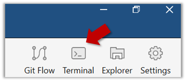
Navigate to the things directory.
Use the command git init which should initialize the repo.
$ git init
Initialized empty Git repository in c:/repos/things/.git/
You can use the command ls -a to view all files, which should show the .git directory that was created by the previous command.
$ ls -a
.  ..  .git
You can also use the git status command to check the status of the newly-created repo. It should respond with something like the bellow
git status
⤵️
# On branch master
#
# Initial commit
#
nothing to commit (create/copy files and use "git add" to track)
Create an empty repo.
Create a file named fruits.txt in the working directory and add some dummy text to it.
Working directory: The directory the repo is based in is called the working directory.
Observe how the file is detected by Git.
The file is shown as ‘unstaged’
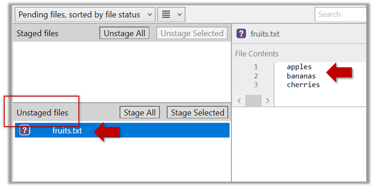
You can use the git status command to check the status of the working directory.
git status
⤵️
# On branch master
#
# Initial commit
#
# Untracked files:
#   (use "git add <file>..." to include in what will be committed)
#
#   a.txt
nothing added to commit but untracked files present (use "git add" to track)
Although git has detected the file in the working directory, it will not do anything with the file unless you tell it to. Suppose we want to commit the current state of the file. First, we should stage the file.
Commit: Saving the current state of the working folder into the Git revision history.
Stage: Instructing Git to prepare a file for committing.
Select the fruits.txt and click on the Stage Selected button
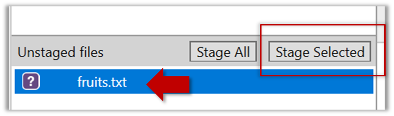
fruits.txt should appear in the Staged files panel now.’
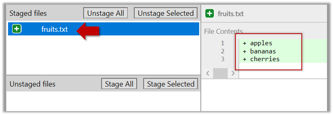
You can use the stage or the add command (they are synonyms, add is the more popular choice) to stage files.
git add fruits.txt
git status
⤵️
# On branch master
#
# Initial commit
#
# Changes to be committed:
#   (use "git rm --cached <file>..." to unstage)
#
#       new file:   fruits.txt
#
Next, we can commit the staged version of fruits.txt
Click the Commit button, enter a commit message e.g. add fruits.txt in to the text box, and click Commit
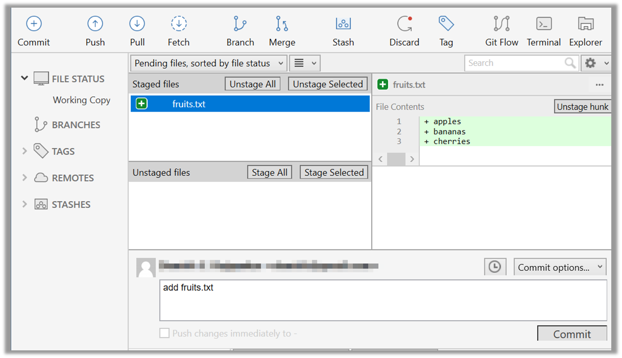
Use the commit command to commit. The -m switch is used to specify the commit message.
git commit -m "add fruits.txt"
You can use the log command to see the commit history
git log
⤵️
commit 8fd30a6910efb28bb258cd01be93e481caeab846
Author: … < … @... >
Date:   Wed Jul 5 16:06:28 2017 +0800

  Add fruits.txt
Note the existence of something called the master branch. Git allows you to have multiple branches (i.e. it is a way to evolve the content in parallel) and Git creates a default branch named master on which the commits
go on by default.
Do some changes to fruits.txt (e.g. add some text and delete some text). Stage the changes, and commit the changes using the same steps we followed before. You should end up with something like this.
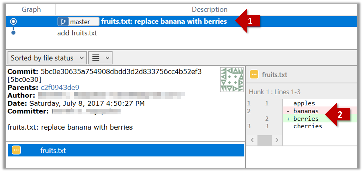
Next, add two more files colors.txt and shapes.txt to the same working directory. Add a third commit to record the current state of the working directory.
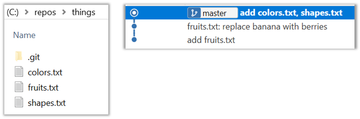
Add a file names temp.txt to the things repo you created. Suppose we don’t want this file to be revision controlled by Git. Let’s instruct Git to ignore temp.txt
The file should be currently listed under Unstaged files. Right-click it and choose Ignore…. Choose Ignore exact filename(s) and click OK.
Observe that a file named .gitignore has been created in the working directory root and has the following line in it.
temp.text
Create a file named .gitignore in the working directory root and add the following line in it.
temp.text
The .gitignore file tells Git which files to ignore when tracking revision history. That file itself can be either revision controlled or ignored.
- To version control it (the more common choice – which allows you to track how the
.gitignorefile changed over time), simply commit it as you would commit any other file. - To ignore it, follow the same steps we followed above when we set Git to ignore the
temp.txtfile.
Tag
Let's tag a commit in a local repo you have (e.g. the sampelrepo-things repo)
Right-click on the commit (in the graphical revision graph) you want to tag and choose Tag…
Specify the tag name e.g. v1.0 and click Add Tag.
The added tag will appear in the revision graph view.
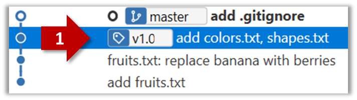
To add a tag to the current commit as v1.0,
git tag –a v1.0
To view tags
git tag
To learn how to add a tag to a past commit, go to the ‘Git Basics – Tagging’ page of the git-scm book and refer the ‘Tagging Later’ section.
Checkout
Git can show you what changed in each commit.
To see which files changed in a commit, click on the commit. To see what changed in a specific file in that commit, click on the file name.
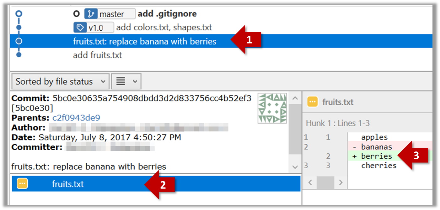
git show < part-of-commit-hash >
Example:
git show 251b4cf
⤵️
commit 5bc0e30635a754908dbdd3d2d833756cc4b52ef3
Author: … < … >
Date:   Sat Jul 8 16:50:27 2017 +0800

    fruits.txt: replace banana with berries

diff --git a/fruits.txt b/fruits.txt
index 15b57f7..17f4528 100644
--- a/fruits.txt
+++ b/fruits.txt
@@ -1,3 +1,3 @@
 apples
-bananas
+berries
 cherries
Git can also show you the difference between two points in the history of the repo.
Select the two points you want to compare using Ctrl+Click.
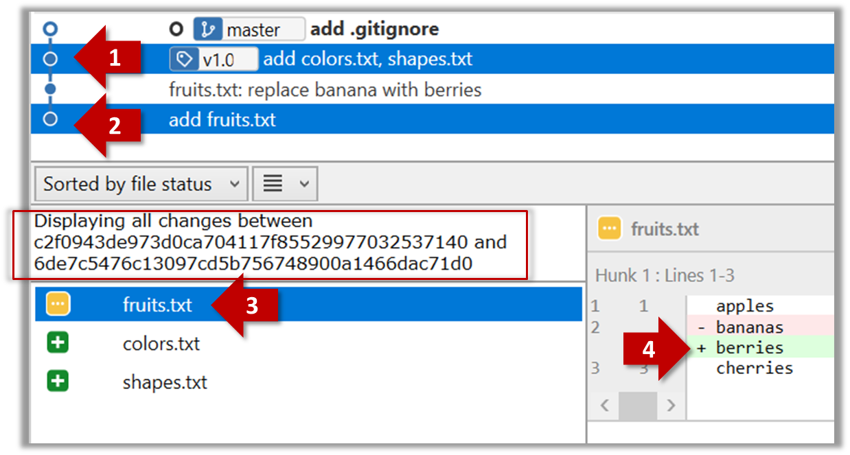
The same method can be used to compare the current state of the working directory (which might have uncommitted changes) to a point in the history.
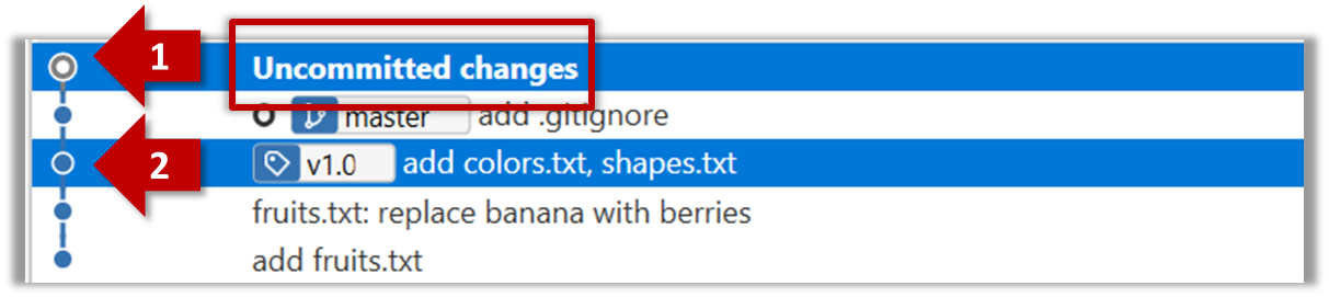
The diff command can be used to view the differences between two points of the history.
git diff: shows the changes (uncommitted) since the last commitgit diff 0023cdd..fcd6199: shows the changes between the points indicated by by commit hashesgit diff v1.0..HEAD: shows changes that happened from the commit tagged asv1.0to the most recent commit.
Git can load a specific version of the history to the working directory. Note that if you have uncommitted changes in the working directory, you need to stash them first to prevent them from being overwritten.
Double-click the commit you want to load to the working directory, or right-click on that commit and choose Checkout....
Click OK to the warning about ‘detached HEAD’ (similar to below).
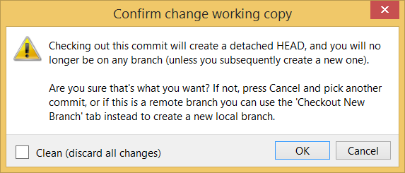
The specified version is now loaded to the working folder, as indicated by the HEAD label. HEAD is a reference to the currently checked out commit.
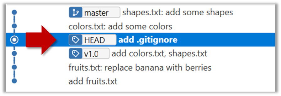
If you checkout a commit that come before the commit in which you added the .gitignore file, Git will now show ignored fiels as ‘unstaged modifications’ because at that stage Git hasn’t been told to ignore those files.
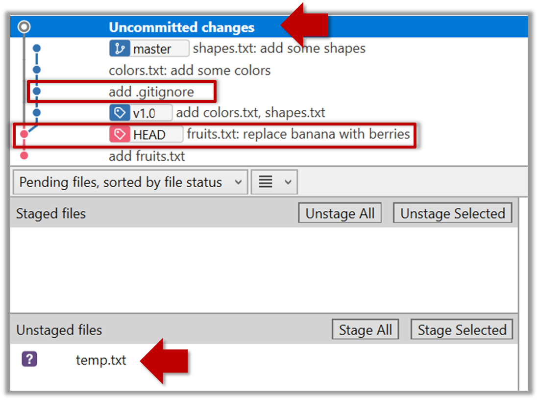
To go back to the latest commit, double-click it.
Use the checkout <commit-identifier> command to change the working directory to the state it was in at a specific past commit.
git checkout v1.0: loads the state as at commit taggedv1.0git checkout 0023cdd: loads the state as at commit with the hash0023cddgit checkout HEAD~2: loads the state that is 2 commits behind the most recent commit
For now, you can ignore the warning about ‘detached HEAD’.
Use the checkout <branch-name> to go back to the most recent commit of the current branch (the default branch in git is named master)
git checkout master
Stash
You can use the git's stash feature to temporarily shelve (or stash) changes you've made to your working copy so that you can work on something else, and then come back and re-apply the stashed changes later on. -- adapted from this
Follow this article from SourceTree creators. Note the GUI shown in the article is slightly outdated but you should be able to map it to the current GUI.
Follow this article from Atlassian.
Clone
Clone the sample repo samplerepo-things to your computer.
Note that the URL of the Github project is different form the URL you need to clone a repo in that Github project. e.g.
Github project URL: https://github.com/nus-cs2103-AY1718S2/samplerepo-things
Git repo URL: https://github.com/nus-cs2103-AY1718S2/samplerepo-things.git (note the .git at the end)
File → Clone / New… and provide the URL of the repo and the destination directory.
You can use the clone command to clone a repo.
Follow instructions given here.
Pull
Clone the sample repo as explained in
Delete the last two commits to simulate cloning the repo 2 commits ago.
Clone
🏆 Can clone a remote repo ![]()
Clone the sample repo samplerepo-things to your computer.
Note that the URL of the Github project is different form the URL you need to clone a repo in that Github project. e.g.
Github project URL: https://github.com/nus-cs2103-AY1718S2/samplerepo-things
Git repo URL: https://github.com/nus-cs2103-AY1718S2/samplerepo-things.git (note the .git at the end)
File → Clone / New… and provide the URL of the repo and the destination directory.
You can use the clone command to clone a repo.
Follow instructions given here.
Right-click the target commit (i.e. the commit that is 2 commits behind the tip) and choose Reset current branch to this commit.
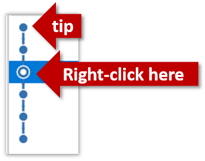
Choose the Hard - … option and click OK.

This is what you will see.
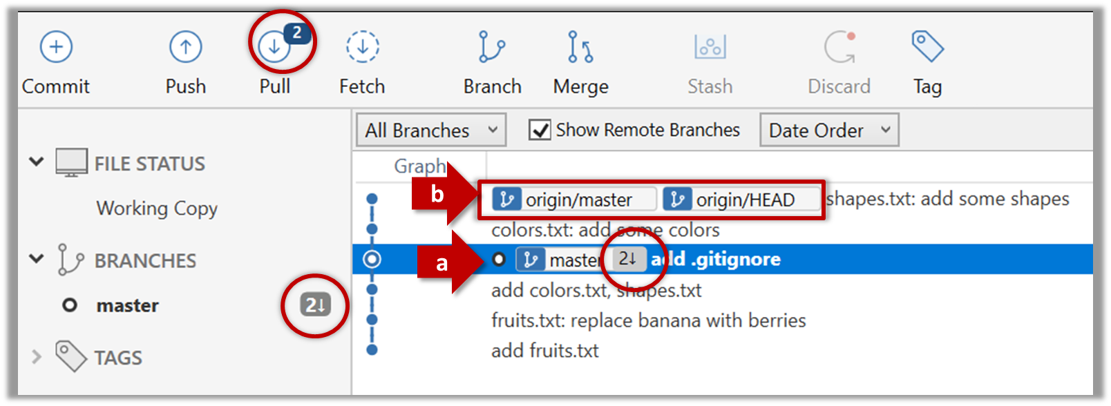
Note the following (cross refer the screenshot above):
(a) The local repo is now at this commit, marked by the master label.
(b) origin/master shows what is the latest commit in the master branch in the remote repo.
Use the reset command to delete commits at the tip of the revision history.
git reset --hard HEAD~2
Now, your local repo state is exactly how it would be if you had cloned the repo 2 commits ago, as if somebody has added two more commits to the remote repo since you cloned it. To get those commits to your local repo (i.e. to sync your local repo with upstream repo) you can do a pull.
Click the Pull button in the main menu, choose origin and master in the next dialog, and click OK.
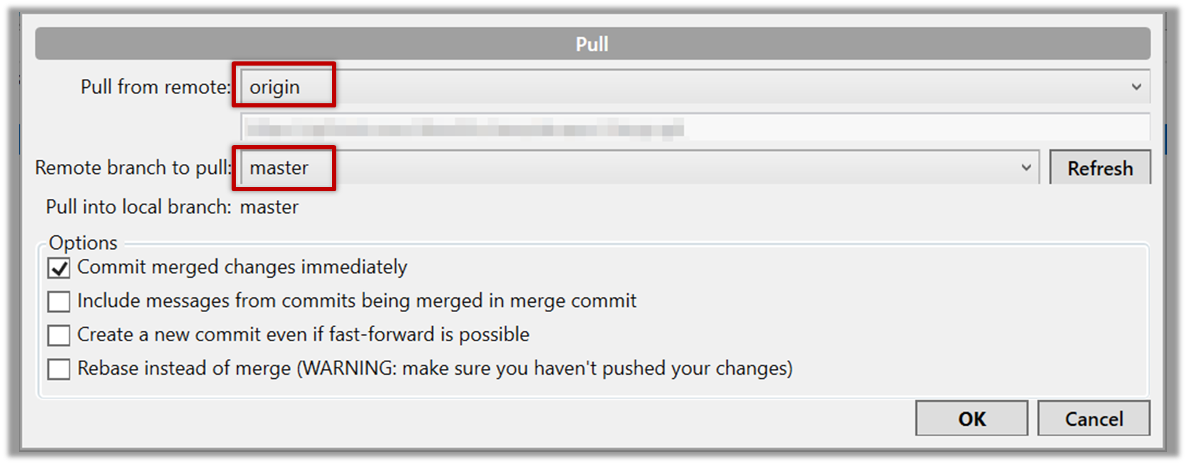
Now you should see something like this where master and origin\master are both pointing the same commit.
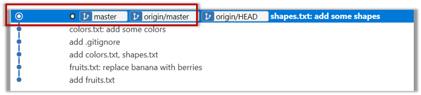
git pull origin
Push
-
Fork the samplerepo-things to your GitHub account:
Navigate to the on GitHub and click on the
 button on the top-right corner.
 -
Clone the fork (not the original) to your computer.
-
Create some commits in your repo.
-
Push the new commits to your fork on GitHub
Click the Push button on the main menu, ensure the settings are as follows in the next dialog, and click the Push button on the dialog.
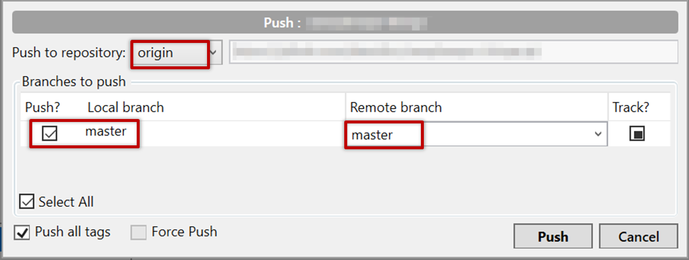
Use the command git push origin master. Enter Github username and password when prompted.
Branch
0. Observe that you are normally in the branch called master. For this, you can take any repo you have on your computer (e.g. a clone of the samplerepo-things).
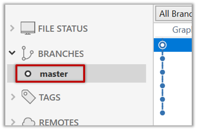
git status
⤵️
on branch master
1. Start a branch named feature1 and switch to the new branch.
Click on the Branch button on the main menu. In the next dialog, enter the branch name and click Create Branch
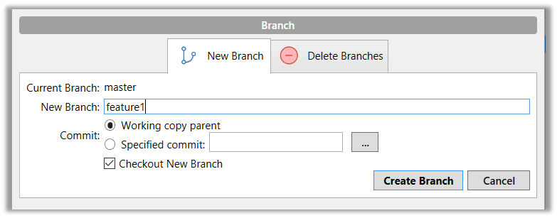
Note how the feature1 is indicated as the current branch.
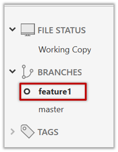
You can use the branch command to create a new branch and the checkout command to switch to a specific branch.
git branch feature1
git checkout feature1
One-step shortcut to create a branch and switch to it at the same time:
git checkout –b feature1
2. Create some commits in the new branch. Just commit as per normal. Commits you add while on a certain branch will become part of that branch.
3. Switch to master branch. Note how the changes you did in the feature1 branch are no longer in the working directory.
Double-click the master branch
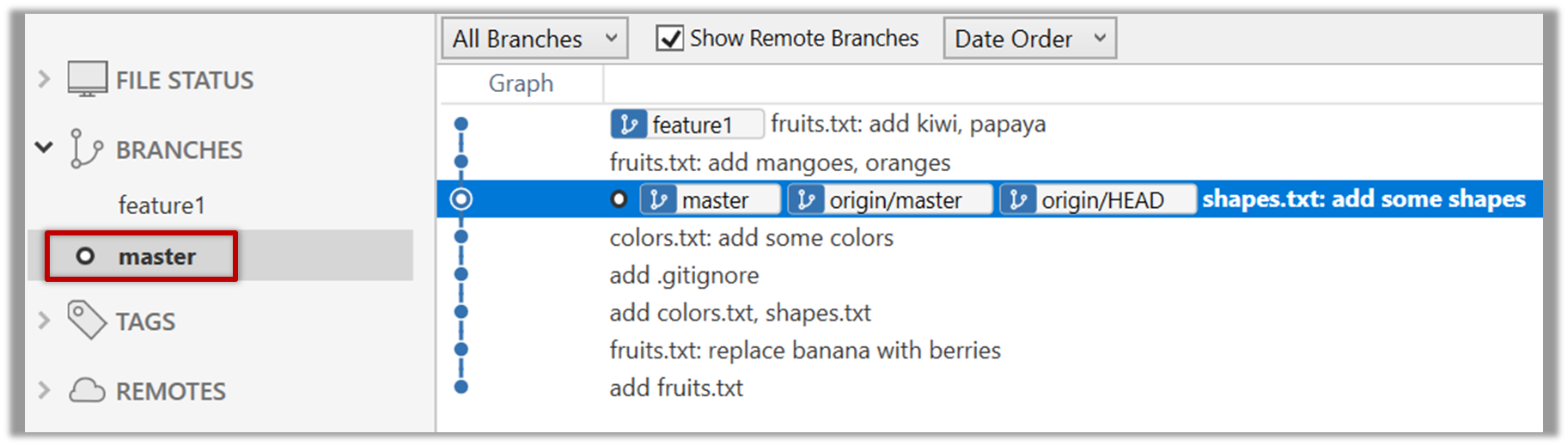
git checkout master
4. Add a commit to the master branch. Let’s imagine it’s a bug fix.
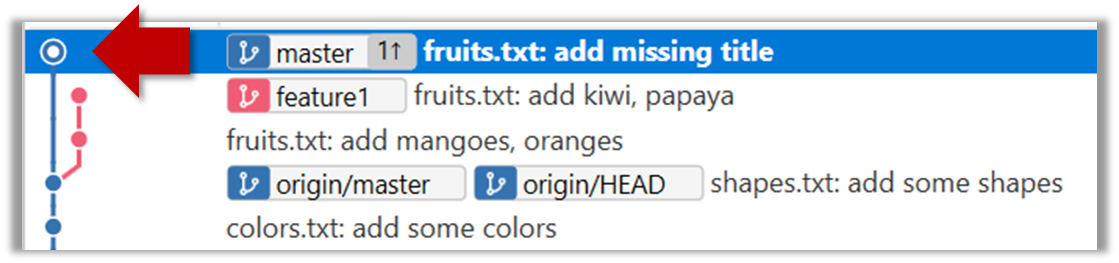
5. Switch back to the feature1 branch (similar to step 3).
6. Merge the master branch to the feature1 branch, giving an end-result like the below. Also note how Git has created a merge commit.
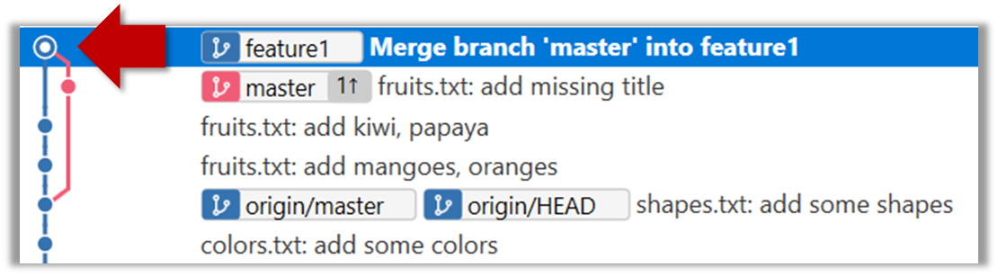
Right-click on the master branch and choose merge master into the current branch. Click OK in the next dialog.
git merge master
Observe how the changes you did in the master branch (i.e. the imaginary bug fix) is now available even when you are in the feature1 branch.
7. Add another commit to the feature1 branch.
8. Switch to the master branch and add one more commit.
9. Merge feature1 to the master branch, giving and end-result like this:
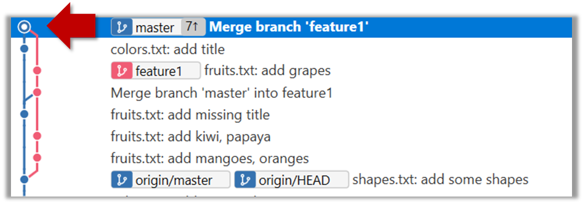
Right-click on the feature1 branch and choose Merge....
git merge feature1
10. Create a new branch called add-countries, switch to it, and add some commits to it (similar to steps 1-2 above). You should have something like this now:
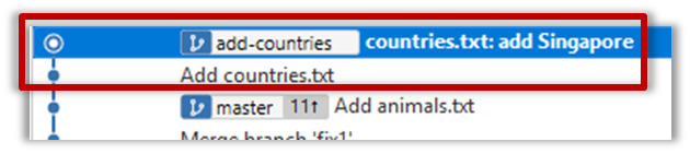
11. Go back to the master branch and merge the add-countries branch onto the master branch (similar to steps 8-9 above). While you might expect to see something
like the below,
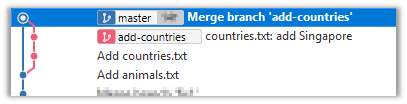
... you are likely to see something like this instead:
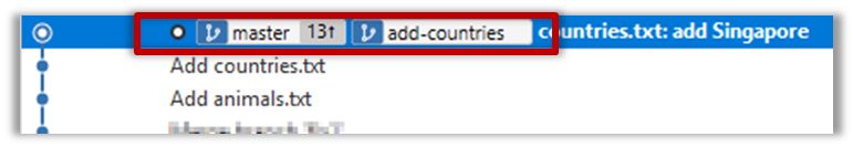
That is because Git does a fast forward merge if possible. Seeing that the master branch has not changed since you started the add-countries branch, Git has decided it is simpler
to just put the commits of the add-countries branch in front of the master branch, without going into the trouble of creating an extra merge commit.
It is possible to force Git to create a merge commit even if fast forwarding is possible.
Tick the box shown below when you merge a branch:
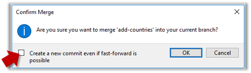
Use the --no-ff switch (short for no fast forward):
git merge --no-ff add-countries
Merge Conflicts
1. Start a branch named fix1 in a local repo. Create a commit that adds a line with some text to one of the files.
2. Switch back to master branch. Create a commit with a conflicting change i.e. it adds a line with some different text in the exact location the previous line was added.
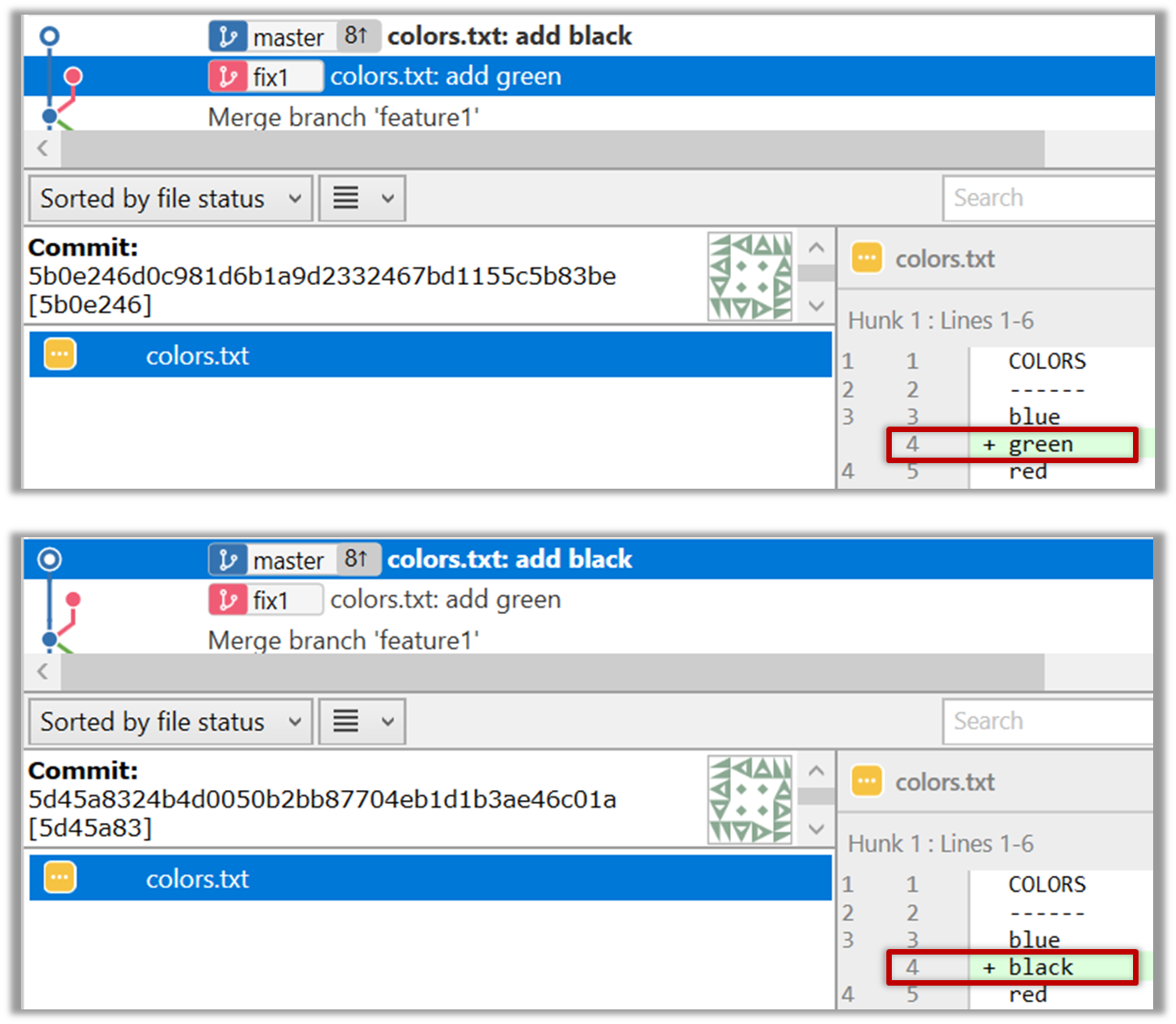
3. Try to merge the fix1 branch onto the master branch. Git will pause mid-way during the merge and report a merge conflict. If you open the conflicted file, you will see something like this:
COLORS
------
blue
<<<<<<< HEAD
black
=======
green
>>>>>>> fix1
red
white
4. Observe how the conflicted part is marked between a line starting with <<<<<<< and a line starting with >>>>>>>, separated by another line starting with
=======.
This is the conflicting part that is coming from the master branch:
<<<<<<< HEAD
black
=======
This is the conflicting part that is coming from the fix1 branch:
=======
green
>>>>>>> fix1
5. Resolve the conflict by editing the file. Let us assume you want to keep both lines in the merged version. You can modify the file to be like this:
COLORS
------
blue
black
green
red
white
6. Stage the changes, and commit.
Create PRs
1. Fork the samplerepo-pr-practice onto your GitHub account. Clone it onto your computer.
2. Create a branch named add-intro in your clone. Add a couple of commits which adds/modifies an Introduction section to the README.md. Example:
# Introduction
Creating Pull Requsts (PRs) is needed when using RCS in a multi-person projects. This repo can be used to practice creating PRs.
3. Push the add-intro branch to your fork.
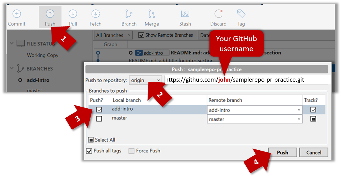
git push origin add-intro
4. Create a Pull Request from the add-intro branch in your fork to the master branch of the same fork (i.e. your-user-name/samplerepo-pr-practice, not se-edu/samplerepo-pr-practice),
as described below.
4a. Go to the GitHub page of your fork (i.e. https://github.com/{your_username}/samplerepo-pr-practice), click on the Pull Requests tab, and then click on New Pull Request button.
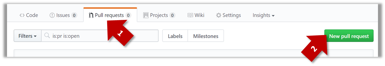
4b. Select base fork and head fork as follows:
base fork: your own fork (i.e.{your user name}/samplerepo-pr-practice, NOTnus-cs2103-AY1718S2/samplerepo-pr-practice)head fork: your own fork.
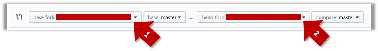
The base fork is where changes should be applied. The head fork contains the changes you would like to be applied.
4c. (1) Set the base branch to master and head branch to add-intro, (2) confirm the diff contains the changes you propose to merge in this PR (i.e. confirm that you did not accidentally include extra commits in the branch),
and (3) click the Create pull request button.
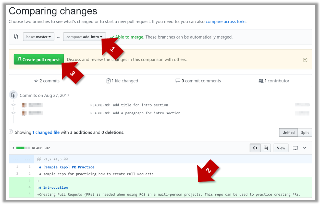
4d. (1) Set PR name, (2) set PR description, and (3) Click the Create pull request button.
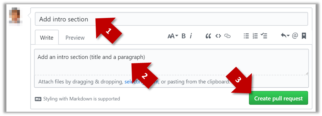
A common newbie mistake when creating branch-based PRs is to mix commits of one PR with another. To learn how to avoid that mistake, you are encouraged to continue and create another PR as explained below.
5. In your local repo, create a new branch add-summary off the master branch.
When creating the new branch, it is very important that you switch back to the master branch first. If not, the new branch will be created off the current branch add-intro. And that is how you end up having commits
of the first PR in the second PR as well.
6. Add a commit in the add-summary branch that adds a Summary section to the README.md, in exactly the same place you added the Introduction section earlier.
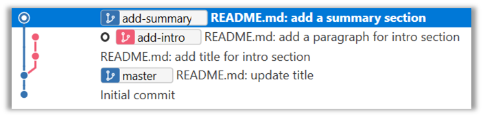
7. Push the add-summary to your fork and create a new PR similar to before.
Manage PRs
1. Go to GitHub page of your fork and review the add-intro PR you created previously in Tools → Git & GitHub → Create PRs to simulate the PR being
reviewed by another developer, as explained below. Note that some features available to PR reviewers will be unavailable to you because you are also the author of the PR.
1a. Go to the respective PR page and click on the Files changed tab. Hover over the line you want to comment on and click on the + icon that appears on the left margin. That should create a text box for you to enter
your comment.
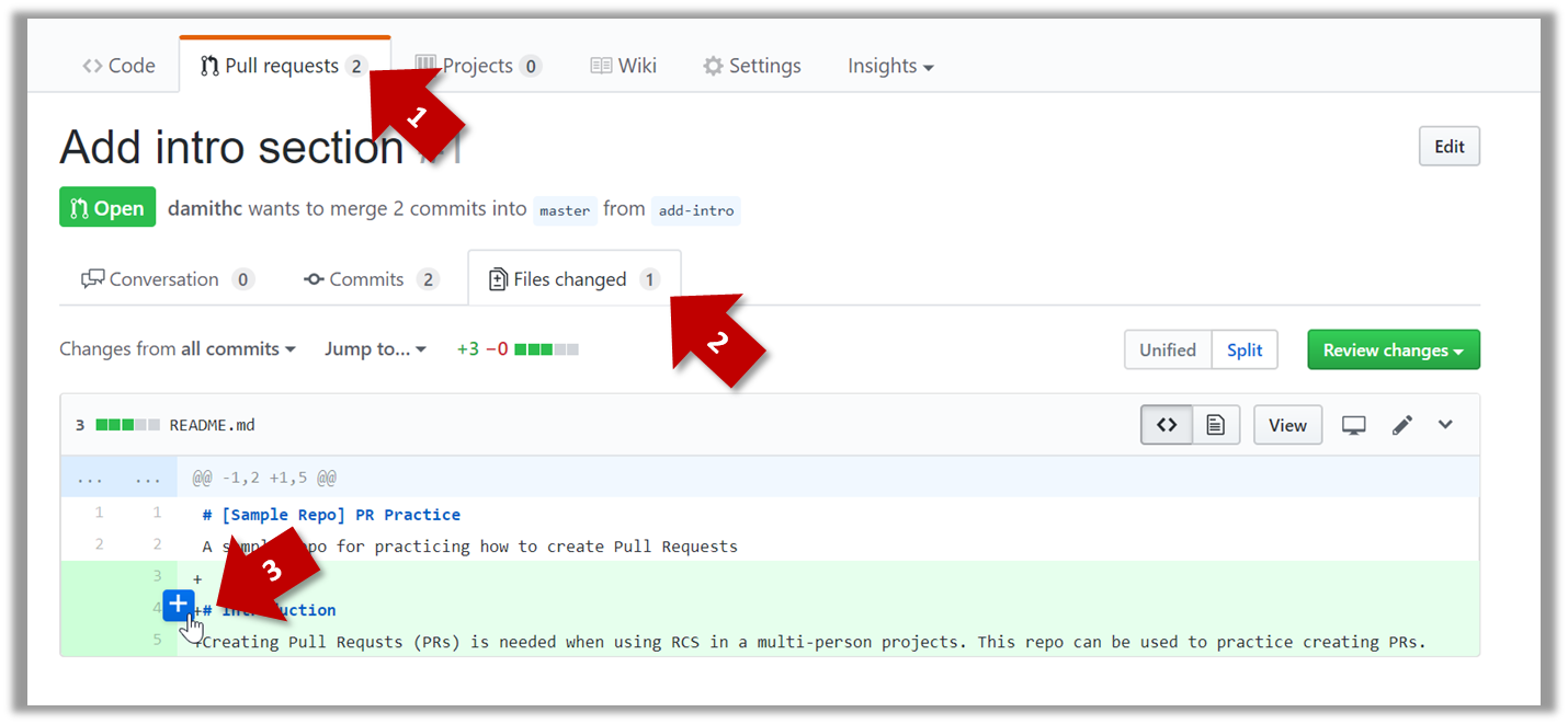
1b. Enter some dummy comment and click on Start a review button.
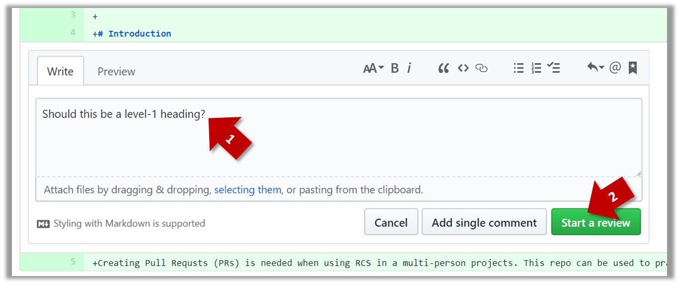
1c. Add a few more comments in other places of the code.
1d. Click on the Review Changes button, enter an overall comment, and click on the Submit review button.
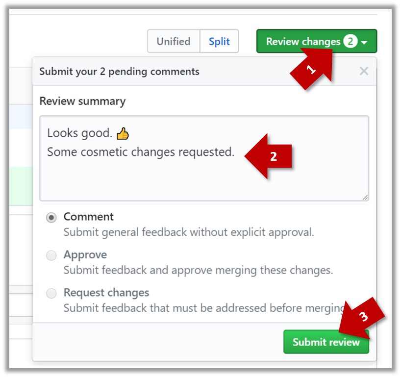
2. Update the PR to simulate revising the code based on reviewer comments. Add some more commits to the add-intro branch and push the new commits to the fork. Observe how the PR is updated automatically to reflect
the new code.
3. Merge the PR. Go to the GitHub page of the respective PR, scroll to the bottom of the Conversation tab, and click on the Merge pull request button, followed by the Confirm merge button.
You should see a Pull request successfully merged and closed message after the PR is merged.
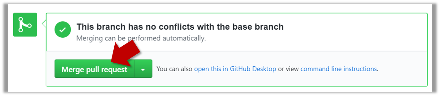
4. Sync the local repo with the remote repo. Because of the merge you did on the GitHub, the master branch of your fork is now ahead of your local repo by one commit. To sync the local repo with the remote repo,
pull the master branch to the local repo.
git checkout master
git pull origin master
Observe how the add-intro branch is now merged to the master branch in your local repo as well.
5. De-conflict the add-summary PR. Note that GitHub page for the add-summary PR is now showing a conflict (when you scroll to the bottom of that page, you should see a message This branch has conflicts that must be resolved).
You can resolve it locally and update the PR accordingly, as explained below.
5a. Switch to the add-summary branch. To make that branch up-to-date with the master branch, merge the master branch to it, which will surface the merge conflict. Resolve it and complete the merge.
5b. Push the updated add-summary branch to the fork. That will remove the 'merge conflicts' warning in the GitHub page of the PR.
6. Merge the add-summary PR using the GitHub interface, similar to how you merged the previous PR.
Note that you could have merged the add-summary branch to the master branch locally before pushing it to GitHub. In that case, the PR will be merged on GitHub automatically to reflect that the branch has been merged
already.
Forking Workflow
-
One member: set up the team org and the team repo.
- Create a GitHub organization for your team. The org name is up to you. We'll refer to this organization as team org from now on.
- Add a team called
developersto your team org. - Add your team members to the
developersteam. - Fork se-edu/samplerepo-workflow-practice to your team org. We'll refer to this as the team repo.
- Add the forked repo to the
developersteam. Give write access.
-
Each team member: create PRs via own fork
- Fork that repo from your team org to your own GitHub account.
- Create a PR to add a file
yourName.md(e.g.jonhDoe.md) containing a brief resume of yourself (branch → commit → push → create PR)
-
For each PR: review, update, and merge.
- A team member (not the PR author): Review the PR by adding comments (can be just dummy comments).
- PR author: Update the PR by pushing more commits to it, to simulate updating the PR based on review comments.
- Another team member: Merge the PR using the GitHub interface.
- All members: Sync your local repo (and your fork) with upstream repo. In this case, your upstream repo is the repo in your team org.
-
Create conflicting PRs.
- Each team member: Create a PR to add yourself under the
Team Memberssection in theREADME.md. - One member: in the
masterbranch, remove John Doe and Jane Doe from theREADME.md, commit, and push to the main repo.
- Each team member: Create a PR to add yourself under the
-
Merge conflicting PRs one at a time. Before merging a PR, you’ll have to resolve conflicts. Steps:
- [Optional] A member can inform the PR author (by posting a comment) that there is a conflict in the PR.
- PR author: Pull the
masterbranch from the repo in your team org. Merge the pulledmasterbranch to your PR branch. Resolve the merge conflict that crops up during the merge. Push the updated PR branch to your fork. - Another member or the PR author: When GitHub does not indicate a conflict anymore, you can go ahead and merge the PR.
Java
Enums
Note that while enumerations are usually a simple set of fixed values, Java enumerations can have behaviors too. To learn how to implement enumerations, read this tutorial (from Oracle)
JavaFX: Basic
Adapted (with permissions) from Marco Jakob's JavaFX 8 tutorial.
JavaFx 8 Tutorial - Part 1: Scene Builder
Introduction
This tutorial will teach you how to create a new JavaFX application in IntelliJ, and to use the SceneBuilder to create a layouts for your application.
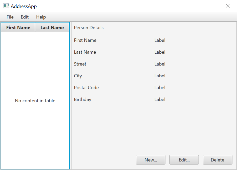
Prerequisites
- Latest Java JDK 8 (includes JavaFX 8)
- IntelliJ (2017.2 or later)
- SceneBuilder 8 (provided by Gluon as Oracle no longer ships the tool in binary form)
Do remember the installation path to SceneBuilder 8 as we will need it to configure IntelliJ in a later step.
IntelliJ Configurations
If this is the first time using IntelliJ, you need to tell IntelliJ where to find JDK 8 and SceneBuilder.
Configuring JDK 8
- On the Welcome screen, press
Configure→Project Default→Project Structure.
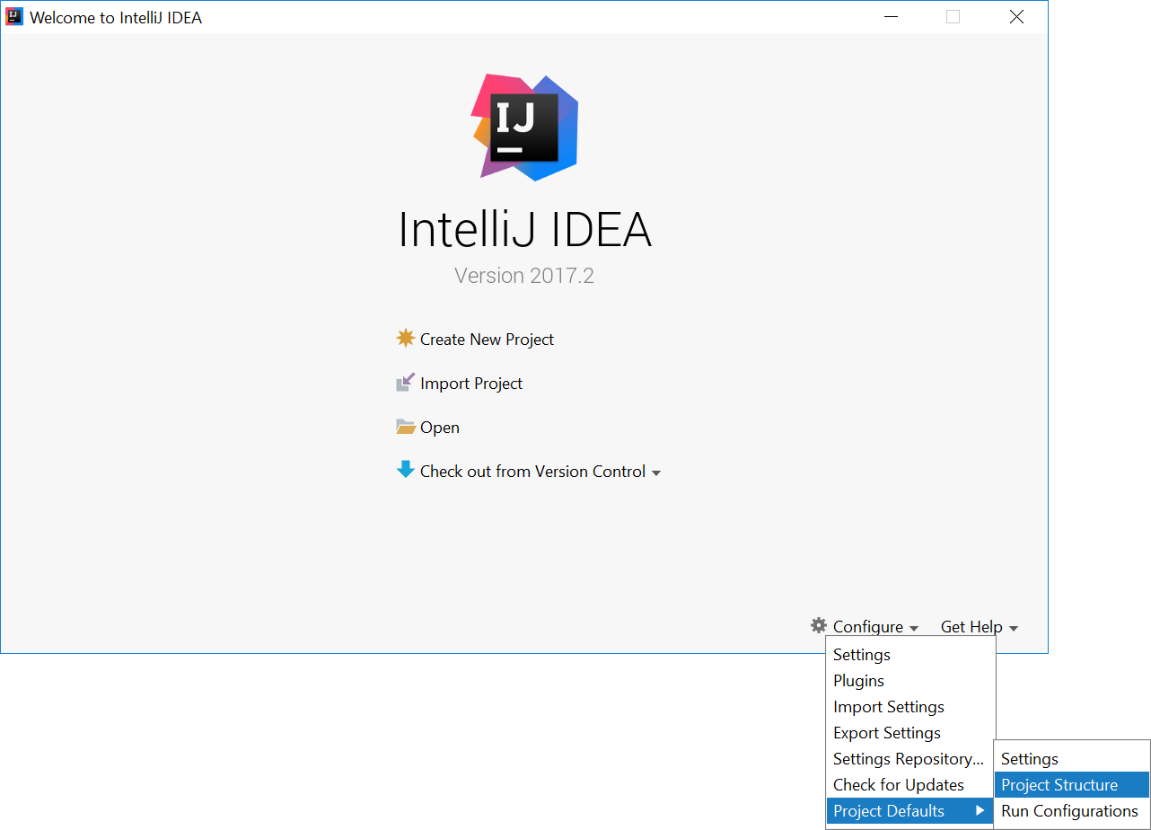
- If you already have a project open, go to the Welcome screen by going to
File→Close Project.
- Under
Project SDK:, pressNew...→JDK. - Select the directory that you install JDK on, and press
OK.
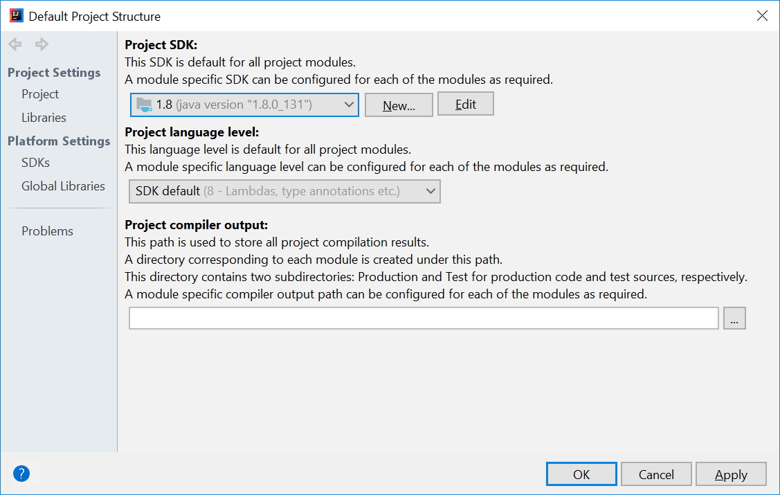
- Press
OKagain.
Configuring Scene Builder
- On the Welcome screen, press
Configure→Settings. - On the left hand side, select
Languages & Frameworks→JavaFX - Under
Path to SceneBuilder:, select the path to where SceneBuilder is installed (e.g.C:\Users\Admin\AppData\Local\SceneBuilder\SceneBuilder.exeon Windows)
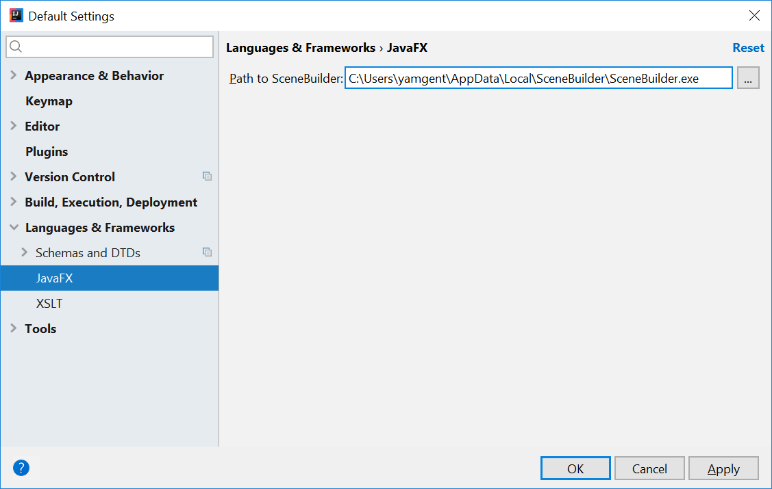
The JavaDocs will come in handy when writing your own JavaFX applications:
Additionally, Oracle also has a tutorial on JavaFX if you are interested.
Create a new JavaFX Project
- On the Welcome screen, press
Create New Project.
- If you already have a project, you can create a new project by going
File→New→Project....
- On the left side, select
JavaFX. Make sure that the Project SDK is set to1.8andJavaFX Applicationis selected.
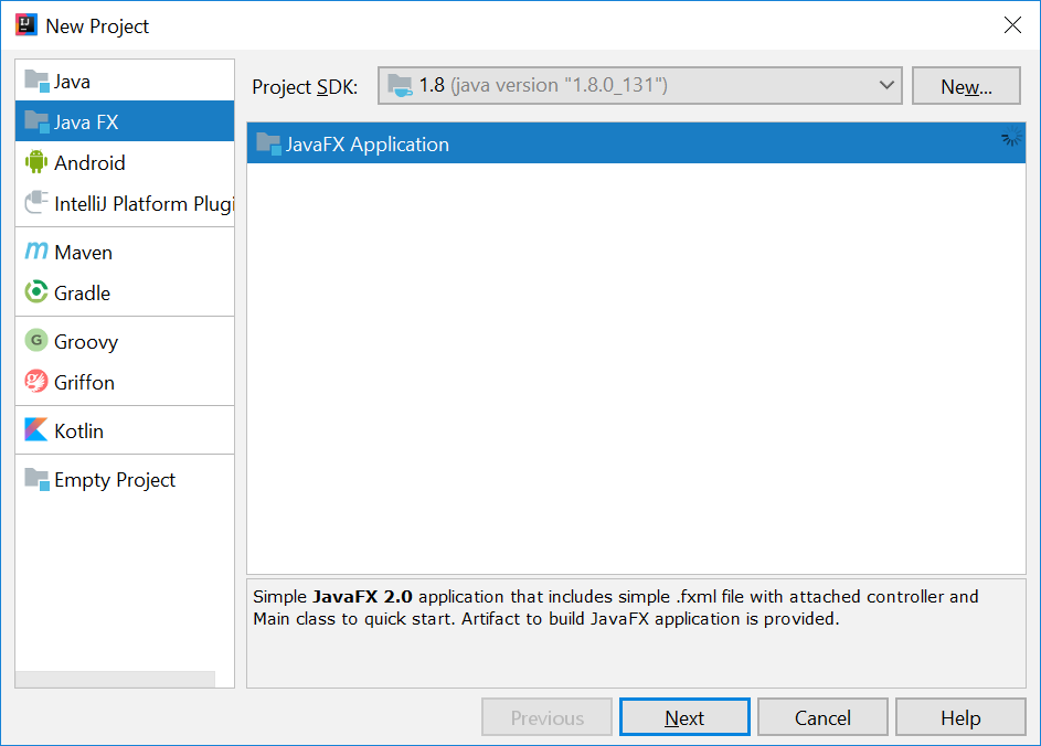
- Press
Next. - Give a name for the application (e.g.
AddressApp), and specify a suitable location. - Press
Finish. If prompted to create a new directory, just pressOK.
Remove the sample package and its content. We will manually create our own package and resources in our tutorial.
Create the Packages
In We will create a package for each of the component. Ensure that your Project pane is open (Alt+1). Right click on the src folder, and select New → Package:
seedu.address- contains the controller classes (i.e. the part that deals with the business logic)seedu.address.model- contains the model classes (i.e. the part that deals with data)seedu.address.view- contains the views (i.e. the part that deals with presenting the data to the user)
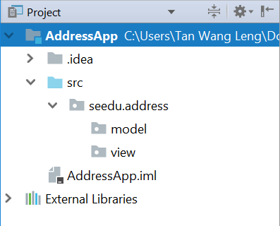
In subsequent tutorials, our view package will also contain some controllers that are directly related to a single view. We will call them view-controllers.
Create the FXML Layout File
There are two ways to create the UI:
- Use FXML, which is an XML format.
- Programmatically create the interface in Java.
We will use FXML for most parts, so that we can separate the view and controller from each other. Furthermore, we are able to use the Scene Builder tool to edit our FXML file. That means we will not have to directly work with XML.
Right click on the view package, and press New → FXML file. For the file name, type PersonOverview.fxml.
Design with Scene Builder
Right-click on PersonOverview.fxml and choose Open with Scene Builder. Now you should see the Scene Builder with just an AnchorPane (visible under Hierarchy on the left).
If IntelliJ prompts for a location of the SceneBuilder executable, make sure to point to where you install SceneBuilder.
- Select the
Anchor Panein your Hierarchy, and adjust the size under Layout (right side). (Pref Width: 600, Pref Height: 300)
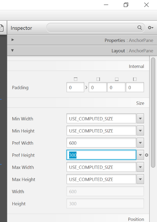
- Add a
Split Pane (Horizontal Flow)(underContainers) by dragging it from the Library into the main area. Right-click theSplit Panein the Hierarchy view and selectFit to Parent.
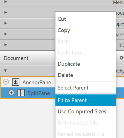
- Drag a
TableView(underControlsin Library view) into the left side of theSplitPane. Select theTableView(not a Column) and set the following layout constraints in the Inspector to theTableView. Inside anAnchorPaneyou can always set anchors to the four borders (see this page for more information on Layouts).
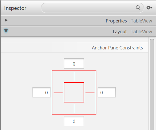
-
Go to the menu
Preview→Show Preview in Windowto see whether the layout configuration is done correctly. Try resizing the window. TheTableViewshould resize together with the window as it is anchored to the borders. -
Change the column text (under Properties) to "First Name" and "Last Name".
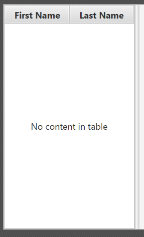
- Select the
TableViewand chooseconstrainted-resizefor the 'Column Resize Policy'. This ensures that the columns will always fill up the entire available space.
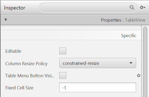
- Add a
Labelon the right side with the text "Person Details:". Adjust the layout using anchors (Top: 5, Left: 5. Right: Blank, Bottom: Blank).
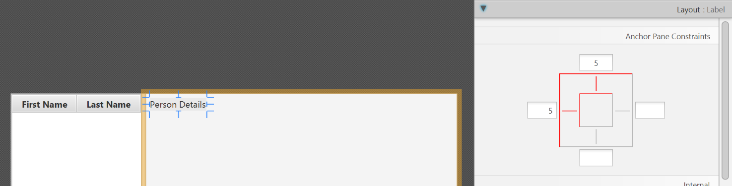
You can use the Search Bar at the top of Library/Inspector to find the respective controls/properties.
- Add a
GridPaneon the right side. Select it, and adjust its layout using anchors (Top: 30, Left: 5, Right: 5, Bottom: Blank).
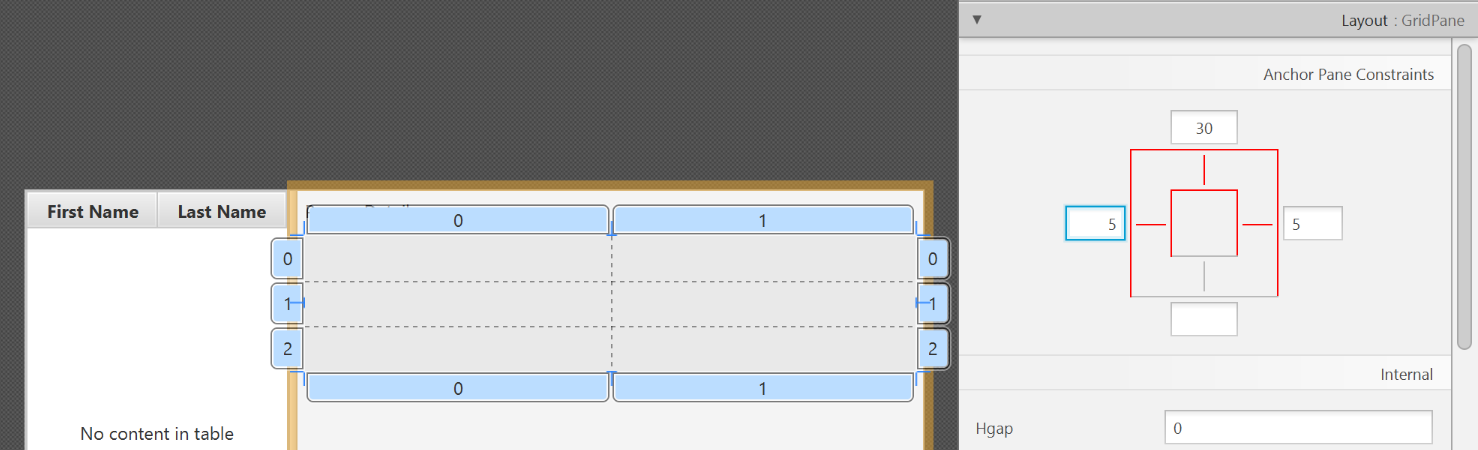
- Add the following labels to the cells, such that the grid is of this form:
| First Name | Label |
|---|---|
| Last Name | Label |
| Street | Label |
| City | Label |
| Postal Code | Label |
| Birthday | Label |
To add a row to the GridPane, select an existing row number, right click the row number and choose "Add Row Below".
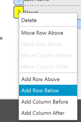
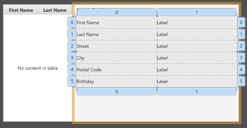
- Add a
ButtonBarat the bottom. Add three buttons to the bar ("New...", "Edit...","Delete"). Adjust the anchors so that it stays at the bottom right (Top: Blank, Left: Blank, Right: 10, Bottom: 5).
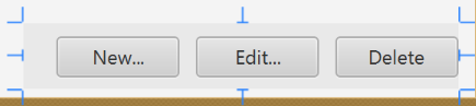
- Now you should see something like the following. Use the
Previewmenu to test its resizing behaviour.
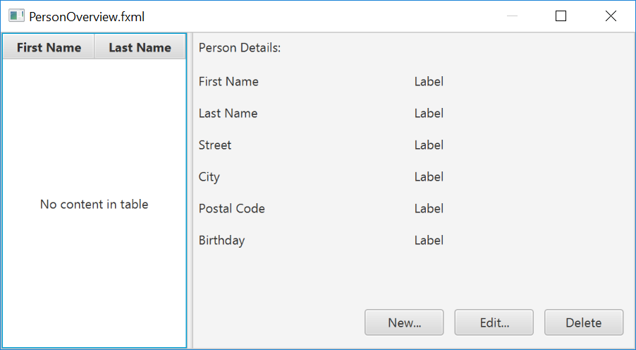
- Save the
.fxmlfile.
Create the Main Application
The PersonOverview.fxml that we just created only contains the content of our entire application. We need another FXML for our root layout, which will contain a menu bar and wraps PersonOverview.fxml.
- Inside IntelliJ, right click on the
viewpackage, and pressNew→FXML file. For the file name, typeRootLayout.fxml. - Right-click on
RootLayout.fxmland chooseOpen with Scene Builder. - Delete the
AnchorPane. We will use another pane for our root layout.
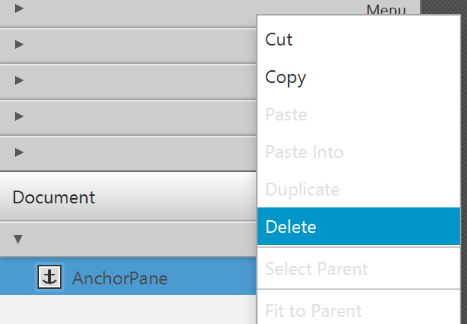
- Add
BorderPaneby dragging it from the Library view into the main area.
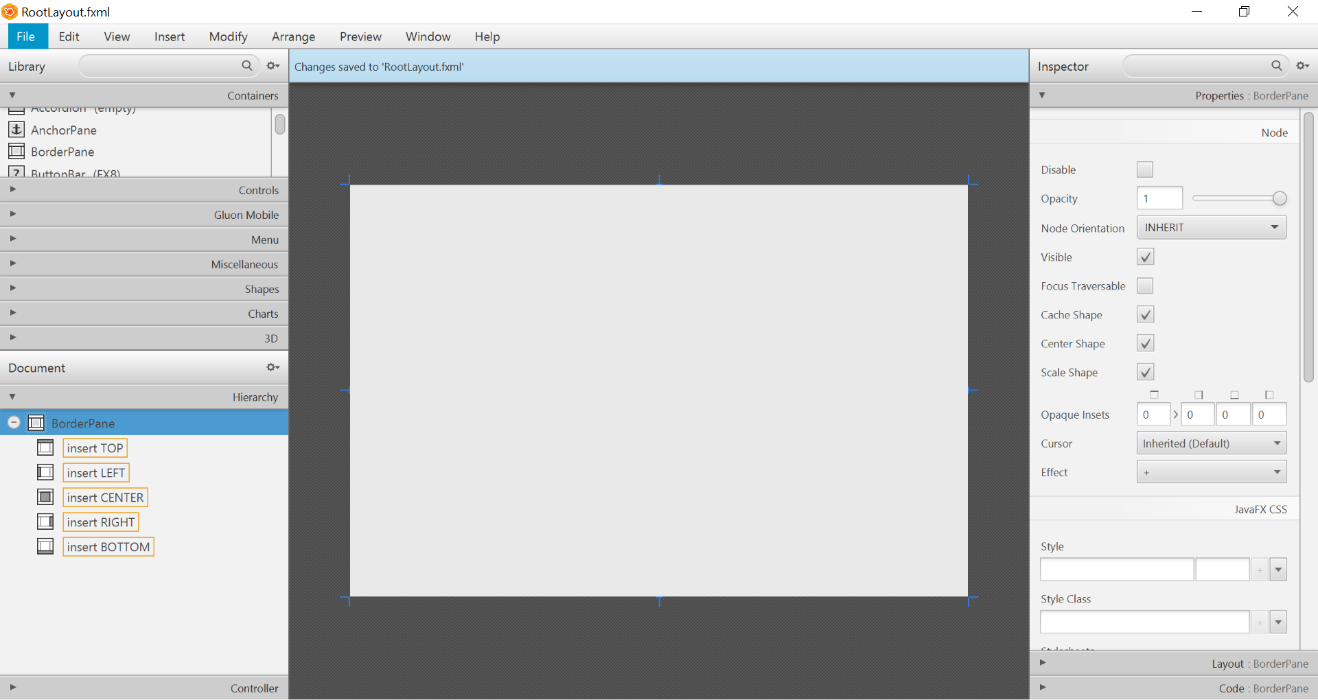
- Resize the
BorderPane(Pref Width: 600, Pref Height: 400)
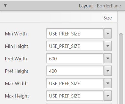
- Add a
MenuBarinto theinsert TOPslot. We will not implement menu functionality for now.
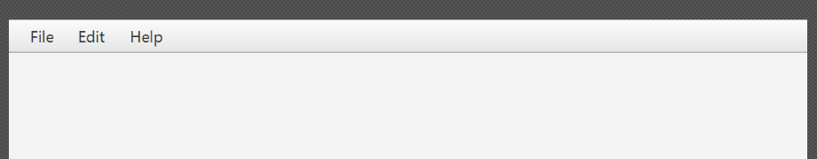
The JavaFX Main Class
Now, we need to create the main Java class that starts up our application with the RootLayout.fxml and adds the PersonOverview.fxml in the center.
Right-click on your seedu.address package, and choose New → JavaFXApplication. For the class name, type MainApp.
The generated MainApp.java class extends from Application and contains two methods. This is the basic structure that we need to start a JavaFX Application. The most important part for us is the start(Stage primaryStage) method. It is automatically called when the application is launch() from within the main() method.
As you see, the start(...) method receives a Stage as parameter. The following graphic illustrates the structure of every JavaFX application:
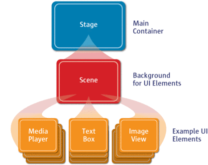
Image Source: http://www.oracle.com
It's like a theater play: The Stage is the main container which is usually a Window with a border and the typical minimize, maximize and close buttons. Inside the Stage you add a Scene which can, of course, be switched out by another Scene. Inside the Scene the actual JavaFX nodes like AnchorPane, TextBox, etc. are added.
See this page fore more info on working with the JavaFX Scene Graph.
Open MainApp.java and replace the code with the following:
MainApp.java
package seedu.address;

import java.io.IOException;

import javafx.application.Application;
import javafx.fxml.FXMLLoader;
import javafx.scene.Scene;
import javafx.scene.layout.AnchorPane;
import javafx.scene.layout.BorderPane;
import javafx.stage.Stage;

public class MainApp extends Application {
    private Stage primaryStage;
    private BorderPane rootLayout;

    @Override
    public void start(Stage primaryStage) {
        this.primaryStage = primaryStage;
        this.primaryStage.setTitle("AddressApp");

        initRootLayout();

        showPersonOverview();
    }

    /**
     * Initializes the root layout.
     */
    public void initRootLayout() {
        try {
            // Load root layout from fxml file.
            FXMLLoader loader = new FXMLLoader();
            loader.setLocation(MainApp.class.getResource("view/RootLayout.fxml"));
            rootLayout = loader.load();

            // Show the scene containing the root layout.
            Scene scene = new Scene(rootLayout);
            primaryStage.setScene(scene);
            primaryStage.show();
        } catch (IOException e) {
            e.printStackTrace();
        }
    }

    /**
     * Shows the person overview inside the root layout.
     */
    public void showPersonOverview() {
        try {
            // Load person overview.
            FXMLLoader loader = new FXMLLoader();
            loader.setLocation(MainApp.class.getResource("view/PersonOverview.fxml"));
            AnchorPane personOverview = loader.load();

            // Set person overview into the center of root layout.
            rootLayout.setCenter(personOverview);
        } catch (IOException e) {
            e.printStackTrace();
        }
    }

    /**
     * Returns the main stage.
     */
    public Stage getPrimaryStage() {
        return primaryStage;
    }

    public static void main(String[] args) {
        launch(args);
    }
}
The various comments should give you some hints about what's going on.
If you run the application now (right click MainApp.java and select Run MainApp.main()), you should see something like this:
Possible Issues
If JavaFx fails to load PersonOverview.fxml, you might get the following error message:
javafx.fxml.LoadException:
/.../AddressApp/out/production/AddressApp/seedu/address/view/PersonOverview.fxml:15
To solve this issue, open PersonOverview.fxml normally in IntelliJ and ensure that there is no such attribute around:
fx:controller="seedu.address.view.PersonOverview"
JavaFx 8 tutorial - Part 2: Model and TableView
Introduction
In this tutorial, we will create the other parts of the application (mainly the model and the controller). We will also use ObservableList and *Property to bind our list of new model's Persons, and
their individual details, to the view, with the controller as the "middleman".
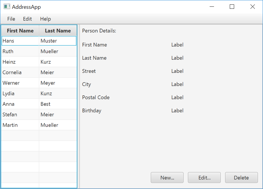
Create the Model class
We need a model class in order to hold information about the people in our address book. Add a new class to the model package (seedu.address.model) called Person. The Person class will
encapsulate the details of an individual person such as name, address and birthday. Add the following code to the class. The JavaFX specifics will be explained after the code snippet.
Person.java
package seedu.address.model;

import java.time.LocalDate;

import javafx.beans.property.IntegerProperty;
import javafx.beans.property.ObjectProperty;
import javafx.beans.property.SimpleIntegerProperty;
import javafx.beans.property.SimpleObjectProperty;
import javafx.beans.property.SimpleStringProperty;
import javafx.beans.property.StringProperty;

/**
 * Model class for a Person.
 */
public class Person {

    private final StringProperty firstName;
    private final StringProperty lastName;
    private final StringProperty street;
    private final IntegerProperty postalCode;
    private final StringProperty city;
    private final ObjectProperty< LocalDate > birthday;

    /**
     * Default constructor.
     */
    public Person() {
        this(null, null);
    }

    /**
     * Constructor with some initial data.
     */
    public Person(String firstName, String lastName) {
        this.firstName = new SimpleStringProperty(firstName);
        this.lastName = new SimpleStringProperty(lastName);

        // Some initial dummy data, just for convenient testing.
        this.street = new SimpleStringProperty("some street");
        this.postalCode = new SimpleIntegerProperty(1234);
        this.city = new SimpleStringProperty("some city");
        this.birthday = new SimpleObjectProperty< LocalDate >(LocalDate.of(1999, 2, 21));
    }

    public String getFirstName() {
        return firstName.get();
    }

    public void setFirstName(String firstName) {
        this.firstName.set(firstName);
    }

    public StringProperty firstNameProperty() {
        return firstName;
    }

    public String getLastName() {
        return lastName.get();
    }

    public void setLastName(String lastName) {
        this.lastName.set(lastName);
    }

    public StringProperty lastNameProperty() {
        return lastName;
    }

    public String getStreet() {
        return street.get();
    }

    public void setStreet(String street) {
        this.street.set(street);
    }

    public StringProperty streetProperty() {
        return street;
    }

    public int getPostalCode() {
        return postalCode.get();
    }

    public void setPostalCode(int postalCode) {
        this.postalCode.set(postalCode);
    }

    public IntegerProperty postalCodeProperty() {
        return postalCode;
    }

    public String getCity() {
        return city.get();
    }

    public void setCity(String city) {
        this.city.set(city);
    }

    public StringProperty cityProperty() {
        return city;
    }

    public LocalDate getBirthday() {
        return birthday.get();
    }

    public void setBirthday(LocalDate birthday) {
        this.birthday.set(birthday);
    }

    public ObjectProperty< LocalDate > birthdayProperty() {
        return birthday;
    }
}
Explanations
- With JavaFX, it is common to use
*Propertyfor all fields of a model class. APropertyallows us, for example, to automatically be notified when thelastNameor any other variable is changed. This helps us keep the view in sync with the data. - To learn more about
*Property, refer to Using JavaFX Properties and Binding LocalDate, the type that we are using forbirthday, is part of the new Date and Time API for JDK 8
A List of Persons
The main data that our application manages is simply a bunch of persons. Let's create a list of Person objects inside the MainApp class. All other controller classes will later get access to that central list inside
the MainApp.
ObservableList
We are working with JavaFX view classes that need to be informed about any changes made to the list of persons. This is important, since otherwise the view would not be in sync with the data. For this purpose, JavaFX introduces some new Collection classes.
Among all these collections, we need the ObservableList. To create a new ObservableList, add the following code at the beginning of the MainApp class. We'll also add a constructor that creates some
sample data and a public getter method:
MainApp.java
// ... AFTER THE OTHER VARIABLES ...

/**
* The data as an observable list of {@link Person}.
*/
private ObservableList< Person > personData = FXCollections.observableArrayList();

    /**
     * Constructor
     */
    public MainApp() {
        // Add some sample data
        personData.add(new Person("Hans", "Muster"));
        personData.add(new Person("Ruth", "Mueller"));
        personData.add(new Person("Heinz", "Kurz"));
        personData.add(new Person("Cornelia", "Meier"));
        personData.add(new Person("Werner", "Meyer"));
        personData.add(new Person("Lydia", "Kunz"));
        personData.add(new Person("Anna", "Best"));
        personData.add(new Person("Stefan", "Meier"));
        personData.add(new Person("Martin", "Mueller"));
    }

    /**
     * Returns the data as an observable list of {@link Person}.
     */
    public ObservableList< Person > getPersonData() {
        return personData;
    }

    // ... THE REST OF THE CLASS ...
The PersonOverviewController
We have our model and view. Let's get our data into our table. We'll need a controller for our PersonOverview.fxml to act as a "middleman" for the model and view.
Create a normal Java class inside the view package called PersonOverviewController.
Note: We must put the class inside the same package as PersonOverview.fxml, otherwise the SceneBuilder won't be able to find it.
We will add some instance variables that give us access to the table and the labels inside the view. The fields and some methods have a special @FXML annotation. This is necessary in order for the .fxml file to
have access to private fields and private methods. After we have everything set up in the .fxml file, the application will automatically fill the variables when the .fxml file is loaded.
So let's add the following code:
Note: Remember to always use the javafx imports, NOT awt or swing.
PersonOverviewController.java
package seedu.address.view;

import javafx.fxml.FXML;
import javafx.scene.control.Label;
import javafx.scene.control.TableColumn;
import javafx.scene.control.TableView;
import seedu.address.MainApp;
import seedu.address.model.Person;

public class PersonOverviewController {
    @FXML
    private TableView< Person> personTable;
    @FXML
    private TableColumn< Person, String> firstNameColumn;
    @FXML
    private TableColumn< Person, String> lastNameColumn;

    @FXML
    private Label firstNameLabel;
    @FXML
    private Label lastNameLabel;
    @FXML
    private Label streetLabel;
    @FXML
    private Label postalCodeLabel;
    @FXML
    private Label cityLabel;
    @FXML
    private Label birthdayLabel;

    // Reference to the main application.
    private MainApp mainApp;

    /**
     * The constructor. It is called before the initialize() method.
     */
    public PersonOverviewController() {
    }

    /**
     * Initializes the controller class. This method is automatically called
     * after the fxml file has been loaded.
     */
    @FXML
    private void initialize() {
        // Initialize the person table with the two columns.
        firstNameColumn.setCellValueFactory(cellData -> cellData.getValue().firstNameProperty());
        lastNameColumn.setCellValueFactory(cellData -> cellData.getValue().lastNameProperty());
    }

    /**
     * Is called by the main application to give a reference back to itself.
     */
    public void setMainApp(MainApp mainApp) {
        this.mainApp = mainApp;

        // Add observable list data to the table
        personTable.setItems(mainApp.getPersonData());
    }
}
Explanations
- All fields and methods where the
.fxmlfile needs access must be annotated with@FXML.- Actually, only if they are private, but it's better to have them private and mark them with the annotation!
- The
initialize()method is automatically called after the.fxmlfile has been loaded. At this time, all the FXML fields should have been initialized already. - The
setCellValueFactory(...)that we set on the table colums are used to determine which field inside thePersonobjects should be used for the particular column. The arrow->indicates that we're using a Java 8 feature called Lambdas. (Another option would be to use aPropertyValueFactory, but this is not type-safe).
Note:
We're only using StringProperty values for our table columns in this example. When you want to use IntegerProperty or DoubleProperty, the setCellValueFactory(...) must have an additional
asObject():
myIntegerColumn.setCellValueFactory(cellData ->
    cellData.getValue().myIntegerProperty().asObject());
This is necessary because of a bad design decision of JavaFX (see this discussion for more details).
Connecting MainApp with the PersonOverviewController
The setMainApp(...) method must be called by the MainApp class. This gives us a way to access the MainApp object and get the list of Persons and other things. Add the following three lines
to showPersonOverview() the method:
MainApp.java - additional lines to add to showPersonOverview() method
// (.... root layout statement goes here ....)

// Give the controller access to the main app.
    PersonOverviewController controller = loader.getController();
    controller.setMainApp(this);

// (.... catch statement goes here ....)
Your showPersonOverview() method in MainApp should now look like this:
MainApp.java - new showPersonOverview() method
/**
* Shows the person overview inside the root layout.
*/
public void showPersonOverview() {
    try {
        // Load person overview.
        FXMLLoader loader = new FXMLLoader();
        loader.setLocation(MainApp.class.getResource("view/PersonOverview.fxml"));
        AnchorPane personOverview = loader.load();

        // Set person overview into the center of root layout.
        rootLayout.setCenter(personOverview);

        // Give the controller access to the main app.
        PersonOverviewController controller = loader.getController();
        controller.setMainApp(this);
    } catch (IOException e) {
        e.printStackTrace();
    }
}
Hook the View to the controller
We're almost there! But one thing is missing: We haven't told our PersonOverview.fxml file which controller to use, and which element should match to which field inside the controller.
- Open
PersonOverview.fxmlwith the SceneBuilder. - Open the Controller group on the left side (just below Hierarchy), and select the
seedu.address.view.PersonOverviewControlleras the controller class.
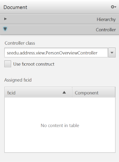
- Select the
TableViewin the Hierarchy group. - In the Inspector view, under the Code group, set 'fx:id' to
personTable.
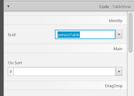
- Do the same for the table columns. Select
firstNameColumnandlastNameColumnfor the 'fx:id' respectively. - For each label in the second column of the grid pane, choose the corresponding 'fx:id'.
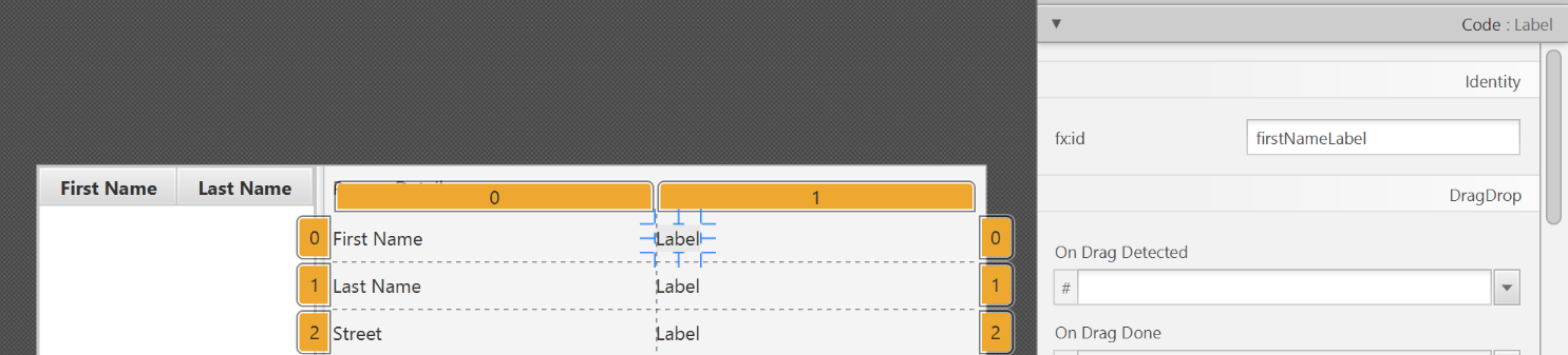
- Save the
.fxmlfile.
Start the Application
When you start your application now, you should see something like this:
Congratulations! The application now shows the list of Persons in the view!
You may notice that selecting a person in the TableView does nothing to the labels at the right side. That is because the user interaction portion has not been programmed yet, which we will cover in the next part of the tutorial.
Streams: Basic
Java 8 introduced a number of new features (e.g. Lambdas, Streams) that are not trivial to learn but also extremely useful to know.
Here is an overview of new Java 8 features . (written by Benjamin Winterberg)
JUnit
JUnit: Basic
JUnit 4 with IntelliJ: A quick introduction -- by DrBFraser
JUnit: Intermediate
Some intermediate JUnit techniques that may be useful:
- It is possible for a JUnit test case to verify if the SUT throws the right exception.
- JUnit Rules are a way to add additional behavior to a test. e.g. to make a test case use a temporary folder for storing files needed for (or generated by) the test.
- It is possible to write methods thar are automatically run before/after a test method/class. These are useful to do pre/post cleanups for example.
- Testing private methods is possible, although not always necessray
SECTION: SUPPLEMENTARY
Principles
Single Responsibility Principle
Single Responsibility Principle (SRP): A class should have one, and only one, reason to change. -- Robert C. Martin
If a class has only one responsibility, it needs to change only when there is a change to that responsibility.
📦 Consider a TextUi class that does parsing of the user commands as well as interacting with the user. That class needs to change when the formatting of the UI changes as well as when the syntax of the user command changes. Hence,
such a class does not follow the SRP.
Interface Segregation Principle
Interface Segregation Principle (ISP): No client should be forced to depend on methods it does not use.
📦 The Payroll class should not depend on the AdminStaff class because it does not use the arrangeMeeting() method. Instead, it should depend on the SalariedStaff interface.
public class Payroll {
    //...
    private void adjustSalaries(AdminStaff adminStaff){ //violates ISP
        //...
    }

}
public class Payroll {
    //...
    private void adjustSalaries(SalariedStaff staff){ //does not violate ISP
        //...
    }
}
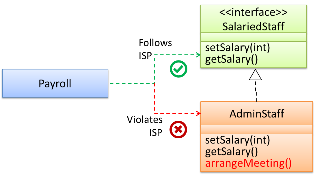
Liskov Substitution Principle
Liskov Substitution Principle (LSP): Derived classes must be substitutable for their base classes. -- proposed by Barbara Liskov
LSP sounds same as
Design → Object Oriented Programming → Inheritance →
Substitutability
Every instance of a subclass is an instance of the superclass, but not vice-versa. As a result, inheritance allows substitutability : the ability to substitute a child class object where a parent class object is expected.
📦 an Academic is an instance of a Staff, but a Staff is not necessarily an instance of an Academic. i.e. wherever an object of the superclass is expected, it can be substituted by
an object of any of its subclasses.
The following code is valid because an AcademicStaff object is substitutable as a Staff object.
Staff staff = new AcademicStaff (); // OK
But the following code is not valid because staff is declared as a Staff type and therefore its value may or may not be of type AcademicStaff, which is the type expected by variable academicStaff.
Staff staff;
...
AcademicStaff academicStaff = staff; // Not OK
📦 Suppose the Payroll class depends on the adjustMySalary(int percent) method of the Staff class. Furthermore, the Staff class states that the adjustMySalary method will work
for all positive percent values. Both Admin and Academic classes override the adjustMySalary method.
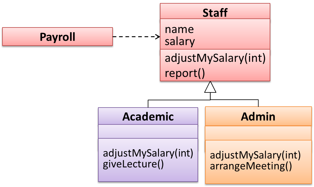
Now consider the following:
Admin#adjustMySalarymethod works for both negative and positive percent values.Academic#adjustMySalarymethod works for percent values1..100only.
In the above scenario,
Adminclass follows LSP because it fulfillsPayroll’s expectation ofStaffobjects (i.e. it works for all positive values). SubstitutingAdminobjects for Staff objects will not break thePayrollclass functionality.Academicclass violates LSP because it will not work for percent values over100as expected by thePayrollclass. SubstitutingAcademicobjects forStaffobjects can potentially break thePayrollclass functionality.
📦 The Rectangle#resize() can take any integers for height and width. This contract is violated by the subclass Square#resize() because it does not accept a height that is
different from the width.
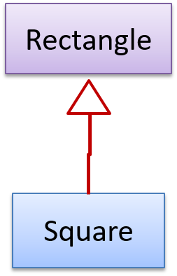
class Rectangle {
    ...
    /** sets the size to given height and width*/
    void resize(int height, int width){
        ...
    }
}


class Square extends Rectangle {

    @Override
    void resize(int height, int width){
        if (height != width) {
            //error
       }
    }
}
Now consider the following method that is written to work with the Rectangle class.
void makeSameSize(Rectangle original, Rectangle toResize){
    toResize.resize(original.getHeight(), original.getWidth());
}
This code will fail if it is called as maekSameSize(new Rectangle(12,8), new Square(4, 4)) That is, Square class is not substitutable for the Rectangle class.
Dependency Inversion Principle
The Dependency Inversion Principle states that,
- High-level modules should not depend on low-level modules. Both should depend on abstractions.
- Abstractions should not depend on details. Details should depend on abstractions.
Example:
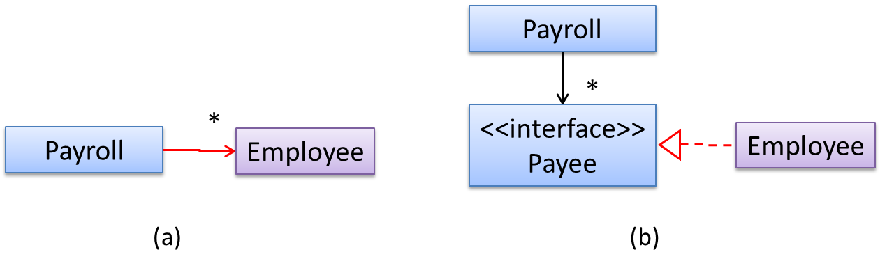
In design (a), the higher level class Payroll depends on the lower level class Employee, a violation of DIP. In design (b), both Payroll and Employee depends on the Payee interface (note
that inheritance is a dependency).
Design (b) is more flexible (and less coupled) because now the Payroll class need not change when the Employee class changes.
Open-Closed Principle
While it is possible to isolate the functionalities of a software system into modules, there is no way to remove interaction between modules. When modules interact with each other, coupling naturally increases. Consequently, it is harder to localize any changes to the software system. The Open-Close Principle aims to alleviate this problem.
Open-Closed Principle (OCP): A module should be open for extension but closed for modification. That is, modules should be written so that they can be extended, without requiring them to be modified. -- proposed by Bertrand Meyer
In object-oriented programming, OCP can be achieved in various ways. This often requires separating the specification (i.e. interface) of a module from its implementation.
📦 In the design given below, the behavior of the CommandQueue class can be altered by adding more concrete Command subclasses. For example, by including a Delete class alongside List, Sort,
and Reset, the CommandQueue can now perform delete commands without modifying its code at all. That is, its behavior was extended without having to modify its code. Hence, it was open to extensions, but closed to
modification.
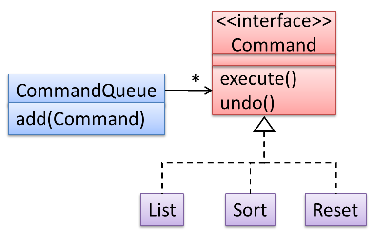
📦 The behavior of a Java generic class can be altered by passing it a different class as a parameter. In the code below, the ArrayList class behaves as a container of Students in one instance and as a container of
Admin objects in the other instance, without having to change its code. That is, the behavior of the ArrayList class is extended without modifying its code.
ArrayList students = new ArrayList< Student >();
ArrayList admins = new ArrayList< Admin >();
SOLID Principles
The five OOP principles given below are known as SOLID Principles (an acronym made up of the first letter of each principle):
Supplmentary → Principles →
Single Responsibility Principle
Single Responsibility Principle (SRP): A class should have one, and only one, reason to change. -- Robert C. Martin
If a class has only one responsibility, it needs to change only when there is a change to that responsibility.
📦 Consider a TextUi class that does parsing of the user commands as well as interacting with the user. That class needs to change when the formatting of the UI changes as well as when the syntax of the user command changes.
Hence, such a class does not follow the SRP.
- An explanation of the SRP from www.oodesign.com
- Another explanation (more detailed) by Patkos Csaba
- A book chapter on SRP - A book chapter on SRP, written by the father of the principle itself Robert C Martin.
Supplmentary → Principles →
Open-Closed Principle
While it is possible to isolate the functionalities of a software system into modules, there is no way to remove interaction between modules. When modules interact with each other, coupling naturally increases. Consequently, it is harder to localize any changes to the software system. The Open-Close Principle aims to alleviate this problem.
Open-Closed Principle (OCP): A module should be open for extension but closed for modification. That is, modules should be written so that they can be extended, without requiring them to be modified. -- proposed by Bertrand Meyer
In object-oriented programming, OCP can be achieved in various ways. This often requires separating the specification (i.e. interface) of a module from its implementation.
📦 In the design given below, the behavior of the CommandQueue class can be altered by adding more concrete Command subclasses. For example, by including a Delete class alongside List,
Sort, and Reset, the CommandQueue can now perform delete commands without modifying its code at all. That is, its behavior was extended without having to modify its code. Hence, it was open
to extensions, but closed to modification.
📦 The behavior of a Java generic class can be altered by passing it a different class as a parameter. In the code below, the ArrayList class behaves as a container of Students in one instance and as a container
of Admin objects in the other instance, without having to change its code. That is, the behavior of the ArrayList class is extended without modifying its code.
ArrayList students = new ArrayList< Student >();
ArrayList admins = new ArrayList< Admin >();
Which of these is closest to the meaning of the open-closed principle?
(a)
Explanation: Please refer the handout for the definition of OCP.
Supplmentary → Principles →
Liskov Substitution Principle
Liskov Substitution Principle (LSP): Derived classes must be substitutable for their base classes. -- proposed by Barbara Liskov
LSP sounds same as
Design → Object Oriented Programming → Inheritance →
Substitutability
Every instance of a subclass is an instance of the superclass, but not vice-versa. As a result, inheritance allows substitutability : the ability to substitute a child class object where a parent class object is expected.
📦 an Academic is an instance of a Staff, but a Staff is not necessarily an instance of an Academic. i.e. wherever an object of the superclass is expected, it can be substituted
by an object of any of its subclasses.
The following code is valid because an AcademicStaff object is substitutable as a Staff object.
Staff staff = new AcademicStaff (); // OK
But the following code is not valid because staff is declared as a Staff type and therefore its value may or may not be of type AcademicStaff, which is the type expected by variable academicStaff.
Staff staff;
...
AcademicStaff academicStaff = staff; // Not OK
📦 Suppose the Payroll class depends on the adjustMySalary(int percent) method of the Staff class. Furthermore, the Staff class states that the adjustMySalary method
will work for all positive percent values. Both Admin and Academic classes override the adjustMySalary method.
Now consider the following:
Admin#adjustMySalarymethod works for both negative and positive percent values.Academic#adjustMySalarymethod works for percent values1..100only.
In the above scenario,
Adminclass follows LSP because it fulfillsPayroll’s expectation ofStaffobjects (i.e. it works for all positive values). SubstitutingAdminobjects for Staff objects will not break thePayrollclass functionality.Academicclass violates LSP because it will not work for percent values over100as expected by thePayrollclass. SubstitutingAcademicobjects forStaffobjects can potentially break thePayrollclass functionality.
📦 The Rectangle#resize() can take any integers for height and width. This contract is violated by the subclass Square#resize() because it does not accept a height that is different from the width.
class Rectangle {
    ...
    /** sets the size to given height and width*/
    void resize(int height, int width){
        ...
    }
}


class Square extends Rectangle {

    @Override
    void resize(int height, int width){
        if (height != width) {
            //error
       }
    }
}
Now consider the following method that is written to work with the Rectangle class.
void makeSameSize(Rectangle original, Rectangle toResize){
    toResize.resize(original.getHeight(), original.getWidth());
}
This code will fail if it is called as maekSameSize(new Rectangle(12,8), new Square(4, 4)) That is, Square class is not substitutable for the Rectangle class.
If a subclass imposes more restrictive conditions than its parent class, it violates Liskov Substitution Principle.
True.
Explanation: If the subclass is more restrictive than the parent class, code that worked with the parent class may not work with the child class. Hence, the substitutability does not exist and LSP has been violated.
Supplmentary → Principles →
Interface Segregation Principle
Interface Segregation Principle (ISP): No client should be forced to depend on methods it does not use.
📦 The Payroll class should not depend on the AdminStaff class because it does not use the arrangeMeeting() method. Instead, it should depend on the SalariedStaff interface.
public class Payroll {
    //...
    private void adjustSalaries(AdminStaff adminStaff){ //violates ISP
        //...
    }

}
public class Payroll {
    //...
    private void adjustSalaries(SalariedStaff staff){ //does not violate ISP
        //...
    }
}
Supplmentary → Principles →
Dependency Inversion Principle
The Dependency Inversion Principle states that,
- High-level modules should not depend on low-level modules. Both should depend on abstractions.
- Abstractions should not depend on details. Details should depend on abstractions.
Example:
In design (a), the higher level class Payroll depends on the lower level class Employee, a violation of DIP. In design (b), both Payroll and Employee depends on the Payee interface
(note that inheritance is a dependency).
Design (b) is more flexible (and less coupled) because now the Payroll class need not change when the Employee class changes.
Which of these statements is true about the Dependency Inversion Principle.
- a. It can complicate the design/implementation by introducing extra abstractions, but it has some benefits.
- b. It is often used during testing, to replace dependencies with mocks.
- c. It reduces dependencies in a design.
- d. It advocates making higher level classes to depend on lower level classes.
Explanation: Replacing dependencies with mocks is Dependency Injection, not DIP. DIP does not reduce dependencies, rather, it changes the direction of dependencies. Yes, it can introduce extra abstractions but often the benefit can outweigh the extra complications.
Separation of Concerns Principle
Separation of Concerns Principle (SoC): To achieve better modularity, separate the code into distinct sections, such that each section addresses a separate concern. -- Proposed by Edsger W. Dijkstra
A concern in this context is a set of information that affects the code of a computer program.
📦 Examples for concerns:
- A specific feature, such as the code related to
add employeefeature - A specific aspect, such as the code related to
persistenceorsecurity - A specific entity, such as the code related to the
Employeeentity
Applying
📦 If the code related to persistence is separated from the code related to security, a change to how the data are persisted will not need changes to how the security is implemented.
This principle can be applied at the class level, as well as on higher levels.
📦 The
Design → Architecture → Styles → n-Tier Style
What
In the n-tier style, higher layers make use of services provided by lower layers. Lower layers are independent of higher layers. Other names: multi-layered, layered.
📦 Operating systems and network communication software often use n-tier style.
This principle should lead to higher
Design → Design Fundamentals → Coupling →
What
Coupling is a measure of the degree of dependence between components, classes, methods, etc. Low coupling indicates that a component is less dependent on other components. High coupling (aka tight coupling or strong coupling) is discouraged due to the following disadvantages:
- Maintenance is harder because a change in one module could cause changes in other modules coupled to it (i.e. a ripple effect).
- Integration is harder because multiple components coupled with each other have to be integrated at the same time.
- Testing and reuse of the module is harder due to its dependence on other modules.
📦 In the example below, design A appears to have a more coupling between the components than design B.
Discuss the coupling levels of alternative designs x and y.
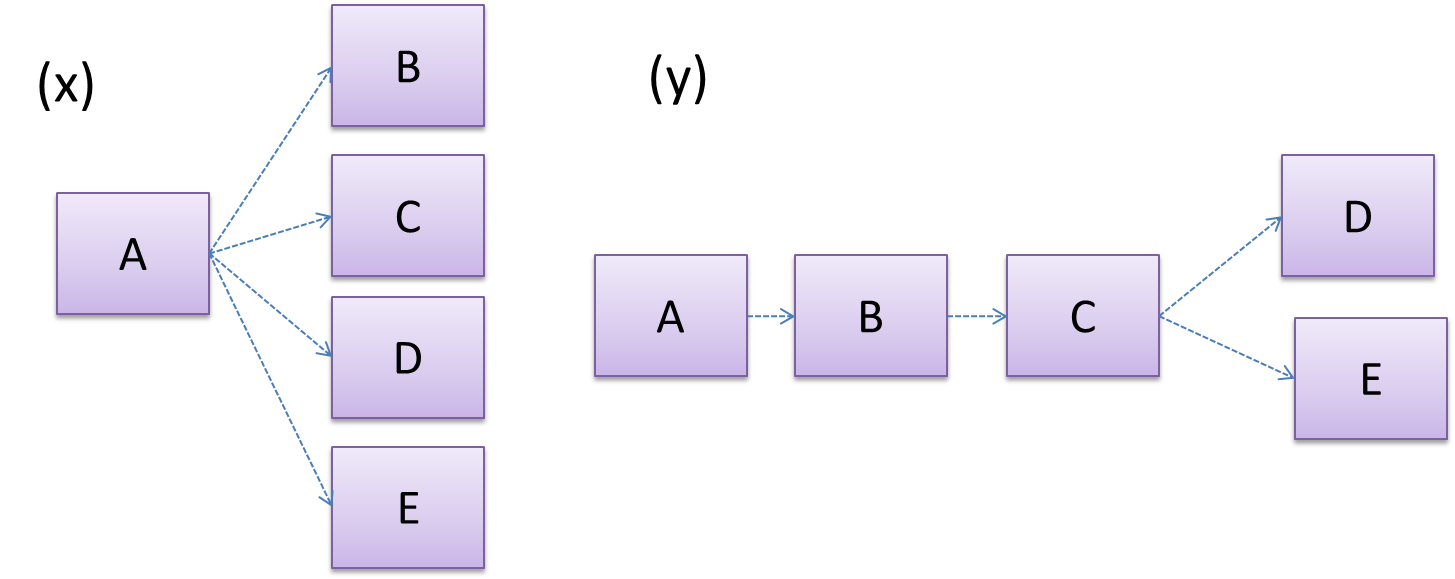
Overall coupling levels in x and y seem to be similar (neither has more dependencies than the other). (Note that the number of dependency links is not a definitive measure of the level of coupling. Some
links may be stronger than the others.). However, in x, A is highly-coupled to the rest of the system while B, C, D, and E are standalone (do not
depend on anything else). In y, no component is as highly-coupled as A of x. However, only D and E are standalone.
Explain the link (if any) between regressions and coupling.
When the system is highly-coupled, the risk of regressions is higher too e.g. when component A is modified, all components ‘coupled’ to component A risk ‘unintended behavioral changes’.
Discuss the relationship between coupling and
Coupling decreases testability because if the
Choose the correct statements.
- a. As coupling increases, testability decreases.
- b. As coupling increases, the risk of regression increases.
- c. As coupling increases, the value of automated regression testing increases.
- d. As coupling increases, integration becomes easier as everything is connected together.
- e. As coupling increases, maintainability decreases.
(a)(b)(c)(d)(e)
Explanation: High coupling means either more components require to be integrated at once in a big-bang fashion (increasing the risk of things going wrong) or more drivers and stubs are required when integrating incrementally.
Design → Design Fundamentals → Cohesion →
What
Cohesion is a measure of how strongly-related and focused the various responsibilities of a component are. A highly-cohesive component keeps related functionalities together while keeping out all other unrelated things.
Higher cohesion is better. Disadvantages of low cohesion (aka weak cohesion):
- Impedes the understandability of modules as it is difficult to express module functionalities at a higher level.
- Lowers maintainability because a module can be modified due to unrelated causes (reason: the module contains code unrelated to each other) or many many modules may need to be modified to achieve a small change in behavior (reason: because the code realated to that change is not localized to a single module).
- Lowers reusability of modules because they do not represent logical units of functionality.
Law of Demeter
Law of Demeter (LoD):
- An object should have limited knowledge of another object.
- An object should only interact with objects that are closely related to it.
Also known as
- Don’t talk to strangers.
- Principle of least knowledge
More concretely, a method m of an object O should invoke only the methods of the following kinds of objects:
- The object
Oitself - Objects passed as parameters of
m - Objects created/instantiated in
m - Objects from the
direct association of O
📦 The following code fragment violates LoD due to the reason: while b is a ‘friend’ of foo (because it receives it as a parameter), g is a ‘friend of a friend’ (which should be considered a ‘stranger’),
and g.doSomething() is analogous to ‘talking to a stranger’.
void foo(Bar b) {
    Goo g = b.getGoo();
    g.doSomething();
}
LoD aims to reduce coupling by limiting the interaction to a closely related group of classes.
📦 In the example above, foo is already coupled to Bar. Upholding LoD avoids foo being coupled to Goo as well.
📦 An analogy for LoD can be drawn from Facebook. If Facebook followed LoD, you would not be allowed to see posts of friends of friends, unless they are your friends as well. If Jake is your friend and Adam is Jake’s friend, you should not be allowed to see Adam’s posts unless Adam is a friend of yours as well.
Brooks' Law
Brooks' Law: Adding people to a late project will make it later. -- Fred Brooks (author of The Mythical Man-Month)
Explanation: The additional communication overhead will outweigh the benefit of adding extra manpower, especially if done near to a deadline.
YAGNI Principle
YAGNI (You Aren't Gonna Need It!) Principle: Do not add code simply because ‘you might need it in the future’.
The principle says that some capability we presume our software needs in the future should not be built now because the chances are "you aren't gonna need it". The rationale is that we do not have perfect information about the future and therefore some of the extra work we do to fulfill a potential future need might go to waste when some of our predictions fail to materialize.
DRY Principle
DRY (Don't Repeat Yourself) Principle: Every piece of knowledge must have a single, unambiguous, authoritative representation within a system The Pragmatic Programmer, by Andy Hunt and Dave Thomas
This principle guards against duplication of information.
📦 The functionality implemented twice is a violation of the DRY principle even if the two implementations are different.
📦 The value a system-wide timeout being defined in multiple places is a violation of DRY.
[END OF BOOK]